Rather orgasmic to be able to crank up your system loud without the blare.
Link: Kean's common mode choke
Kean using a CM choke for reducing ground noise seems a very good idea, I have never thought of that, it seems that that matter would deserve a thread of his one.
One can also measure the leakage inductance of an unknown CM choke, by shunting one coil and measure the other.
This way the leakage inductance measured 23uH.
One can also measure the leakage inductance of an unknown CM choke, by shunting one coil and measure the other.
Hi, Sergio,
Haven't noticed you post for a while. Good to see you back.
This way the leakage inductance measured 23uH.
That value is well low enough that you shouldn't have any potential issues.
Hi, Sergio,
Haven't noticed you post for a while. Good to see you back.
Have been very busy with others problems.
I need to talk to you, will send email to you soon.
The leakage of these chokes is not very large at all, even for the split-bobbin types; self-resonance is in the hundreds of KHz and that's what the 3.9k resistor is for, to damp it. I have not found it to be an issue.
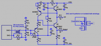
How is this for a schematic? Does it match your PSU setup?
If we put the CM choke at the DAC trafo winding instead, we could use one coil for all channels. For this we will need one coil per channel.
PS. Can you measure the mismatch in inductance between the two side of the CM choke?
How is this for a schematic? Does it match your PSU setup?
If we put the CM choke at the DAC trafo winding instead, we could use one coil for all channels. For this we will need one coil per channel.
PS. Can you measure the mismatch in inductance between the two side of the CM choke?
Attachments
I'm playing around with the same DAC chip (AK4396), and I'm willing to try out using the virtual ground bootstrap idea. 🙂
Have most of the parts lying around in my spare bin, with the exception of the 2700k pot, 15pF cap, and the inductor.
EDIT : If I were to use this to implement a low pass filter as well as the bal -> se conversion, would it be just as simple as placing the components across the + - legs? Or should there be one set each of low pass filter components for both + and - legs, connected to ground?
Anything over 15pF will work for the cap, but lower is better.
I don't know what kind of noise DACs make and where it is best decoupled to. However I would suggest using filtering across the +- outputs rather than individual filters to ground, because a mismatch in the filters will convert CM noise into DM noise which will pass through the CM choke and into the unbalanced output.
The leakage of these chokes is not very large at all, even for the split-bobbin types; self-resonance is in the hundreds of KHz and that's what the 3.9k resistor is for, to damp it. I have not found it to be an issue.
How is this for a schematic? Does it match your PSU setup?
If we put the CM choke at the DAC trafo winding instead, we could use one coil for all channels. For this we will need one coil per channel.
PS. Can you measure the mismatch in inductance between the two side of the CM choke?
It's something like 9.608mH vs 9.592mH.
Unfortunately I don't have the necessary transformer so I must add another one. I guess I will use another enclosure with balanced inputs and a separate transformer.
The CM choke deal is most likely practically useful to combat and remove the "Shout!" "Hard Sound" errata from audio systems.
I checked that and it works.
However, your system does not shout.
Even so, we could use a slightly evil hack to cause it to both shout more and image better for more 3d realistic sound. Reduce those 4 decoupler caps on your power amp to 470uF each. It will image slightly better. I already checked. And magic comes with a price (almost always a headache). Then it will shout just slightly (not a lot). So, if you can then knock off the shout at input, then you will have won the game. I did not detect any treble droop from his circuit. It is a competitor to my own BlareBuster tech, but his works better and they are interoperable, so please install his circuit first. Then, after that, you may add mine if you need more assistance at blare removal. Input transformers and the LightSpeed circuit are also in this same category and all of that is interoperable.
Last edited:
Hi
I refer to the schematic here
The Kuartlotron
I want to build the buffer and would like to ask a few questions
1) What size transformer ? Power consumption per channel ?
2) Can i use BC 547B and 557B transistors?
3) R1 is a 100R trimmer? R5 is 5k trimmer ? I use 56 R for R1 since i donot have distortion anaylser?
4)with regard to L1. How many turns of 20G gauge over the AA batteries ? How close do i need to get 2 uH ?
thanks
kp93300
kp93300
1 strong enough to run the rectifier and regulators which are a much more significant load than the buffers, 2 yes at slightly reduced performance, 3 you can use the values printed instead of the trimmers if you attempt to hfe match the transistors fairly close, 4 about 15 turns of 20ga around 1 AA battery will make the right size coil (the battery is not part of the circuit--tape the wire on it and then rotate the battery to form the coil, and then put the battery back in the clock).
Hi keantoken,
In your write up, you mentioned that R9 could be made into a trimmer if we wanted to trim for less DC offset.
Since there's no 2.7M trimmer where I buy stuff, I was planning on making this into a fixed resistor in series with a trimmer. Which combination would be better? A 2.4M fixed resistor with 300k trimmer, or a 2.5M trimmer with a 200k fixed?
Thanks 🙂
About the low pass filter, from what I understand that it can be anywhere in the analog stage, so I was thinking of just placing it at the single ended output of the Kuartlotron, both to simplify the implementation to the schematic I've seen, as well as to save up on parts. 🙂
Last edited:
The offset trimmer can be anywhere from 2M to 4M. It is rarely more than 3M. I chose 2.7M as the most common value. I would use a 2M resistor with 2M or more trimmer, or something close. Your 2.5M trimmer is fine.
Last edited:
About the low pass filter, from what I understand that it can be anywhere in the analog stage, so I was thinking of just placing it at the single ended output of the Kuartlotron, both to simplify the implementation to the schematic I've seen, as well as to save up on parts. 🙂
This will work, but the DAC already has a 390R or so output resistance, so you could put a cap across the outputs. I think this would be better because it stops noise closer to the source.
The offset trimmer can be anywhere from 2M to 4M. It is rarely more than 3M. I chose 2.7M as the most common value. I would use a 2M resistor with 2M or more trimmer, or something close. Your 2.5M trimmer is fine.
keantoken said:This will work, but the DAC already has a 390R or so output resistance, so you could put a cap across the outputs. I think this would be better because it stops noise closer to the source.
Thanks, will do.
I was double checking my parts bin and found that I don't have enough 470uF caps. Since I'm ordering caps anyway, is there a preference for cap characteristics? Low ESR caps like Panasonic FMs? Would 'boutique' caps like Elna Silmic IIs or Nichicon Muses make a difference? (From the write up I saw that Joachim used this in his implem). I also saw OS-CON SEPCs at the online store that are within the voltage range.
I have no preference. My prototype uses Pana FC, mainly because they were what I have. I haven't thought the caps could be a problem.
Member
Joined 2009
Paid Member
I find that I don't want to take the time and effort to try different brands of caps, waiting for them to 'burn-in' etc. so I just buy Nichicon MUSE caps and don't worry about them.
- Home
- Source & Line
- Analog Line Level
- The Kuartlotron - keantoken's simple error-correction superbuffer