Lazy Cat said:Hi Glen
Just payed the PCB's. 😎
As you've said the amp is already sounding sweet ... nice 🙂
Can you please make some measurements like distortion, output resistance, power BW, slew rate ... 😉 Thanks
Hi Andrej
Time permitting I will perform all these measurments. Currently all tests have been done with a 100pF Cdom capacitor, which I chose as a starting point just to get the amp operational without hassle. Due to the relatively low gm of the valve LTP (compared to a BJT ltp) 100pF is probably overcompensating the amp a fair bit.
I will have to make some proper phase margin and stability measurements to see how low I can go with Cdom first.
Slew rate, bandwidth and distortion will all improve with a lower value Cdom capacitor.
Anyway, even with 100pF for Cdom, the power bandwidth is still pretty good, as can be seen by scope picture of the 100kHz squarewave response I attached to post 173:
http://www.diyaudio.com/forums/showthread.php?postid=1488711#post1488711
The slew rate in this type of topology is essentially determined by the amount of current that the LTP can deliver to charge and discharge the Cdom compensation capacitor.
Because the LTP has a current mirror load to provide push-pull drive to the VAS buffer input and Cdom, the slewing is symetrical and the maximum drive current is equal to the LTP tail current, which is 2mA.
The voltage developed across a capacitors plates by a constant current is equal to:
Vc=(Ic/C)t
Where
Ic = the current in Amperes
C = the capacitance in Farads
t = the time in seconds
With a 100pF Cdom cap and a 2mA tail current, the slew rate can therefore be approximated by Sr=(0.002/100e-12)1e-6 = 20V/us
The amp measured approximately 18V/us. This may seem like a low figure, but it must be viewed in the context of the amplifier output volatge swing. For the amplifiers peak output voltage of only 12.6V for the rated 10W rms into an 8 ohm load, is is still quite OK.
18V/us for 10W rms into 8 ohms is equivalent to 60V/us in an amplifier rated at 100W rms into 8 ohms (40V peak).
The sinusoidal slewrate-limiting full power bandwidth of the amplifier is equal to:
Fmax= Sr / (2pi.Vp)
Where
Sr is the dynamic voltage swing in seconds
Vp is the peak output voltage.
So, with a 100pF Cdom capacitor, the full power (10W rms / 8 ohms)sinusoidal bandwidth is therefore equal to:
18e6 / (6.28 * 12.6V)
= 227kHz.
The small signal bandwidth was measured to be ~270kHz.
Cheers,
Glen
Bonsai said:...only you also need to remove the plants.
OK 😀
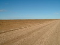
This bit of landscape known as the "Moon Plain". Not far from where some of the Mad Max filming was done. I wanted to photograph the tourist sign promoting this fact the last time I went through that way but some b@stard souvenired it.
Attachments

Hi Glen
The boards were delivered today and they are good quality, well done.
Can't wait to load them up and start trying some different NOS ECC83 tubes. I have Telefunken smooth and ribbed plate, Mullard, Siemens, and all the other usual suspects all NOS.
Thanks for all of your efforts on this.
Cheers
Gary..
😎
I have just go to visit Oz.
It it's anything like the part of the world I come from, the shotgun is used to blow holes in road signs.
No kidding.
😀
It it's anything like the part of the world I come from, the shotgun is used to blow holes in road signs.
No kidding.
😀
Arizona ? Texas ?
Unfortunately I can't find one online ...
...but I vividly remember all those:
"no shooting across highways" - signs with a bunch of bullet holes in them 😱


Unfortunately I can't find one online ...
...but I vividly remember all those:
"no shooting across highways" - signs with a bunch of bullet holes in them 😱
gary s said:Hi Glen
The boards were delivered today and they are good quality, well done.
Can't wait to load them up and start trying some different NOS ECC83 tubes. I have Telefunken smooth and ribbed plate, Mullard, Siemens, and all the other usual suspects all NOS.
Thanks for all of your efforts on this.
Cheers
Gary..
😎
G'day Gary.
Glad you're happy with the boards. As stated previously, the only thing still up for revision is the value of the compensation capacitor.
I'll do my best to get this done over the long weekend, but if you get your boards up and running before, just install the conservative 100pF cap for compensation capacitor C4 as listed on the current BOM on my website. However, I'll think you'll find that the amp will still work quite fine in the meanwhile 🙂
I will also update the website with construction / wiring recommendations, etc.
A few points to get everyone going in the meanwhile:
The Vbe multiplier circuit used to bias the output stage has an inherent negative temperature coefficient. This means that the class A bias will reduce a little once the amplifier has warmed up.
In my amp, with the bias current set to the desired 800mA with the amplifier cold, reduced to about 720mA once the heatsink reached equilibrium with the amplifier sitting idle for a couple of hours.
So the bias trimpot just needs a little ‘hot’ tweak.
The bias current is easily measured during set up (with the audio input terminal shorted to ground please) by measuring the voltage across resistors R18 and R19 - 350mV for 800mA Iq.
Also, importantly, before turning the amplifier on for the first time, make sure that the bias trimpot is turned down for minimum resistance, so that the initial bias current is zero.
The bias should also be adjusted in small increments, each time allowing the bias voltage to stabilise. C5 slows it down a little.
Other than that, don’t be too surprised up the amount of 100Hz / 120Hz hum emanating from the speakers when you power it up without any audio source connected to the input, if you haven’t wired in the suggested 10k volume potentiometer. This is perfectly normal.
The input impedance of the amplifier is quite large at 500k, so an open-circuit input will readily pick up mains hum. The amplifiers biasing voltage divider R1, R2, R3 also partly relies on the shunting effect of the low output impedance of a source to practically eliminate the coupled supply rail ripple.
Once you plug in a source, the amp is dead silent.
Have fun!
Cheers,
Glen
EDIT: Another couple of things.
Even so the collector of MJ2955 PNP output transistor is connected to ground, it should still be insulated from the heatsink bracket as this is not the ideal place to connect the amplifier ground to the chassis and ground loops are not wanted.
The only electrical connection to from ground to the chassis should be directly from the negative terminal of the 10,000uF filter capacitor.
Also, do not connect the amplifier ground to the chassis at the input RCA connector (use an RCA connector that is chassis insulated)
The ~1uH output inductor consists of 13 turns of 1mm diameter enamaled copper wire wound on a 10mm drill bit.
The best way to wire up the output L//R+C is at the speaker terminals / binding posts as shown in the photo I attached to post 168:
http://www.diyaudio.com/forums/showthread.php?postid=1488171#post1488171
Bonsai said:I have just go to visit Oz.
It it's anything like the part of the world I come from, the shotgun is used to blow holes in road signs.
No kidding.
😀
It's used for American tourists.
😀
Guitar Amp....?
Hi Glen,
This is not my usual sort of thing but nice job anyway!
Should work fine also as a guitar power amp, wondering if
anyone might get around to try it. Might make a nice small
project for my son, we'll see. Thinking of a pair, high bias
class AB raising the supply for 30W each ...
Still, I prefer a split supply with no output cap, have to think
about it a bit more.
Pete B.
...bias current set to the desired 800mA with the amplifier cold, reduced to about 720mA once the heatsink reached equilibrium with the amplifier sitting idle for a couple of hours.
So the bias trimpot just needs a little ‘hot’ tweak.
Glen
- What (Conrad?) heatsink are you using in your amp? (...hoping I haven't overlooked a thing)
...you might want to put that and your 1uH fabrication recipe into the BOM 😉
- C4 with 500V seems pretty hard to grab for me but 100pF, 100V, +/- 2% should be acceptable - correct?
vrun said:100pF, 100V, +/- 2% should be acceptable - correct?
And the no-signal voltage level on the base of Q4 is ?
vrun said:
Glen
- What (Conrad?) heatsink are you using in your amp? (...hoping I haven't overlooked a thing)
...you might want to put that and your 1uH fabrication recipe into the BOM 😉
- C4 with 500V seems pretty hard to grab for me but 100pF, 100V, +/- 2% should be acceptable - correct?
Hi vrun
I am using the MF30-75 heatsink. However, a better option would be the MF30-1F-75 which is the same thing, but it has a machined 35mm X 6mm semiconductor mounting flange.
A 100V capacitor for C4 is too low. I bought my 500V silver mica capacitors from Farnell:
http://au.farnell.com/jsp/search/br...ch_001&Ntt=silver+mica&Ntx=&_requestid=141008
RS Components also stock them, but (over here at least) at a higher price with a minimum order quantity of 5 units.
500V is higher than required, but the 500V range of silver mica capacitors are commonly avaliable and are not to expensive in values 100pF and under. Most suppliers of tubes and associated components for valve amplifiers stock them also.
Cheers,
Glen
Re: Guitar Amp....?
Hi Pete.
Thanks for the kind words. I would think that class A with (currently only simulated) ~0.01% THD-20 is a little extravagant for guitar use, but it's a cheap amp and should still work fine anyway.
For a direct coupled higher power version you will have to wait for the K25A 😉
Cheers,
Glen
PB2 said:Hi Glen,
This is not my usual sort of thing but nice job anyway!
Should work fine also as a guitar power amp, wondering if
anyone might get around to try it. Might make a nice small
project for my son, we'll see. Thinking of a pair, high bias
class AB raising the supply for 30W each ...
Still, I prefer a split supply with no output cap, have to think
about it a bit more.
Pete B.
Hi Pete.
Thanks for the kind words. I would think that class A with (currently only simulated) ~0.01% THD-20 is a little extravagant for guitar use, but it's a cheap amp and should still work fine anyway.
For a direct coupled higher power version you will have to wait for the K25A 😉
Cheers,
Glen
ooops... ...proof that I've never been toobedAnd the no-signal voltage level on the base of Q4 is ?
 ...thanks Jacco & Glen
Glen,
as I am standing "below your feet & in reverse" it's going to be another supplier - sp thanks and the data will have to suffice ....
MF30-1F-75 C/Watt for 80 °C rise 0.37 ...there is some fine heatsink manufacturers around.
100pF Mica 500V ... still looking since RS components is "out".
Which presumably is going to be 25Watts RMS then ?...will have to wait for the K25A
BTW: What are you simulating the circuit with ? (Spice version)
Would you mind sending that simulation file ?
Hi,
NOS Philips and Siemens ECC83 tubes.
Pure beauty 😉
NOS Philips and Siemens ECC83 tubes.
An externally hosted image should be here but it was not working when we last tested it.
Pure beauty 😉
4fun said:Hi,
NOS Philips and Siemens ECC83 tubes.
Pure beauty 😉
Ok, I'll take them. 🙂
EDIT: A Goodwill expedition netted me a vintage receiver with 2 each 2SA627 and 2SD188. I guess I'll be using these. 😉
MJL21193 said:
Ok, I'll take them. 🙂
EDIT: A Goodwill expedition netted me a vintage receiver with 2 each 2SA627 and 2SD188. I guess I'll be using these. 😉
Hey, I found the datasheet for the 2SA627, but not for the 2SD188.
These parts seem to be obsolete, but fT for the 2SA627 is specified as 15MHz. Nice find. I had no idea that trannies suitable for low power audio this fast came in TO-3. I'm assuming that the 2SD188 is the complement with an equally high fT.
Be wary of a potential for parasitic oscillation if these devices are used in this design.
Vrun, I'm using LT spice. The complete sim file will go up on the website once I've tidied it up.
Cheers,
Glen
G.Kleinschmidt said:
Hey, I found the datasheet for the 2SA627, but not for the 2SD188.
These parts seem to be obsolete, but fT for the 2SA627 is specified as 15MHz. Nice find. I had no idea that trannies suitable for low power audio this fast came in TO-3. I'm assuming that the 2SD188 is the complement with an equally high fT.
Be wary of a potential for parasitic oscillation if these devices are used in this design.
The data sheets are in the "Japanese Transistor Manual 1981", first Google hit would be Data sheet archive.
It lists fT as 10 for both.
These are obsolete, but I do a fair bit of "dumpster diving" looking for stuff that might have some quality components.
These were used for the Hiraga 20W Class-A amp, so they should be ok.
How to tame the oscillation if it occurs? Base stoppers maybe?
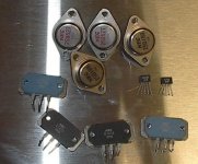
Here they are, with other goodies (relatively good anyway, for what they cost).
2SA705A, 2SD745A - 140V/10A/15MHz outputs
2SA798 50V dual monolithic high gain (250-1200) PNP
2SC2291 100V dual monolithic high gain(250-1200) NPN
The other usual suspects: transformers, heatsinks, etc.
2SA705A, 2SD745A - 140V/10A/15MHz outputs
2SA798 50V dual monolithic high gain (250-1200) PNP
2SC2291 100V dual monolithic high gain(250-1200) NPN
The other usual suspects: transformers, heatsinks, etc.
Attachments
- Status
- Not open for further replies.
- Home
- Amplifiers
- Solid State
- The Kleinschmidt 10A