Hi,
I have NOS Siemens ECC83 to use in this app. 🙂
Radioman62 said:
I wote for the use of ECC83
I have NOS Siemens ECC83 to use in this app. 🙂
bear said:Just some random thoughts, now that I went back and peer'd at the schetch-o-matic... I understand that simplicity is/was the idea, and that it was/is a worked out and prototyped working circuit... and I didn't read every post in the thread - so sorry if someone said this before...
But the achilles heel of this has got to be the blocking cap at the output?
Would not it be better to find a CT ground at the PS, for the benefit of the output, servo if necessary (gack!), and/or use two power supplies? The PS for the toobe would be fairly tiny and cheap...
Radioman62 said:
You don't need any DC protection circuit for this amp. Thats good. John Broskie at Tubecad like this kind of basic, safe designs. I think he is a high valued authority when it comes to ampdesigns. (mostly when it's tubes involved though)
An alternative double PSU design would probably gather even more interrest. I'm with you Bear . But I don't know if Glen would like to split the design up in to many flavours.
I would personally like to have a double pair of output transistors and maybe about 15watt power in 8 ohm. Mostly because i have some beutiful heatzinks ready for it. But then again, you have to compromise and settle the design to get it done. This fast easy to get design from Glen is a splendid project we all could compare with each other when done. Its also possible to tinker with it and do your own mods on it, if you really want, I think 🙂
Design issue #2, explained here:
http://www.diyaudio.com/forums/showthread.php?postid=1459581#post1459581
The K10A is rated at 10W class A into 4 ohms and 20W class AB into 4 ohms. However, there is no reason why a bigger capacity PSU cannot be added with the bias turned up for class A to 20W into 4 ohms. The pair of TO-3's can certainly cope with the dissipation.
I'm working on a direct coupled bipolar rail 25W class A in 8 ohms, 50W class AB into 4 ohm hybrid design with all the bells and whistles (cascoded 6SN7 LTP, folded cascode VAS, DC protection, power up timer, regulated HV, etc) but I won't design the PCB for it until this design is over and done with. It will also be a lot more expensive to build, so it isn't really a substitute for this design.
Cheers,
Glen
Corloc said:I'm afraid I'm going to have to bow out on my two boards. 🙁
OK, no problem
I've updated the list (this time realizing that I need to include myself too 🙄 ):
Me – 2 boards.
Jacco - 6 boards
Mike W - 2 boards
Radioman62 - 2 boards
MJL21193 - 2 boards
gary s - 2 boards
Lazy cat - 2 boards
spind – 2 boards
4fun – 2 boards
poynton - 2 boards
tony.garner – 2 boards
Stoolpigeon - 2 boards
22 boards of 50 remaining.
The boards are due on Friday, so if I'm lucky enough for them to arrive on schedule, I'll have a pair built up and tested this weekend. Then I'll be happy to put the full design details up with pics.
Cheers,
Glen
gary s said:Hi Glen.
Thanks for the update, keep us informed you are doing a good job.
Regards
Gary..
No worries gary.
Unfortunately the boards didn't turn up today and the guy that is handling my order at the board house seems to be having the day off.

Oh well, at least my ordered range of silver mica caps for use in / empirically selecting the compensation capacitor turned up this morning.
Will chase the boards up on Monday.
Hi Glen,
Having most parts on hand, this will be a nice spring project.
Please sign me up for 2 boards.
Thanks
Detlef
Having most parts on hand, this will be a nice spring project.
Please sign me up for 2 boards.
Thanks
Detlef
OK, I just rang up. Boards are currently being routed, will be sent out this afternoon. I will get them tomorrow morning.
Will finally have a pair built up this weekend.
Cheers,
Glen
Will finally have a pair built up this weekend.
Cheers,
Glen
Guys, some good news and some bad news.
I got the boards today, but not without some hassle as they were sent to the wrong address, even so I explicitly stressed my preferred delivery address to the manufacturer over the phone just yesterday well before dispatch. 😡
And there is another problem. In my original e-mail to the manufacturer I requested for a quotation on the manufacture of 20 boards. As per the company’s usual procedure, they replied with a quotation for not just the manufacturing cost of 20 boards, but 30,40 and 50 as well.
When I rang the manufacturer to verbally confirm my acceptance of their quotation and have the job go ahead, I requested the 50 board option. However, this request was not fulfilled and I only received 20 boards.
I will see what I can sort out over the phone tomorrow, but since I only confirmed the 50 board order verbally over the phone, I may not have much success.
I’m really sorry about this, but unfortunately I have to warn that a few of those last to put their names down last on the list may have to miss out. 🙁
Now, on a more happy and productive note, the boards are of excellent quality and I will be posting up the beginnings of the webpage devoted to the design later tonight (if I get time, otherwise tomorrow night)
This will start with a comprehensive schematic incorporating most component values as well as the off board L//R+C combined output coupling and RFI suppression network that I recommend the amplifier be used with, as well as input signal RFI filtering at the input jack, used in conjunction with an optional volume or line level control potentiometer.
Cheers,
Glen
Attachments
You can change my number to 2 boards to serve a few more from the lot of 20, i hate kids anyway.
(also means my stash of Neccie SB600/SD555 will be less contaminated)
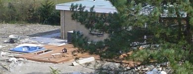
After a 4 year struggle, my classic-Bentley wrenching building inspection head dude at city hall stated last week that likely by the end of the year it's finally permitted to have the swimming pool overhere covered.
Fortunately, with a nextdoor neighbour having a whirlpool and sun terrace construction in progress, there's always a substitute to annoy me.
Cheers from the home reno front.
(also means my stash of Neccie SB600/SD555 will be less contaminated)
After a 4 year struggle, my classic-Bentley wrenching building inspection head dude at city hall stated last week that likely by the end of the year it's finally permitted to have the swimming pool overhere covered.
Fortunately, with a nextdoor neighbour having a whirlpool and sun terrace construction in progress, there's always a substitute to annoy me.
Cheers from the home reno front.
Attachments
You're a gentleman Jacco. But lets see what I can arrange with the PCB manufacturer tomorrow.
Here is the link to the webpage:
http://users.picknowl.com.au/~glenk/K10A.HTM
Not much yet but it is a start!
I will do my best to get the first unit fully built and tested over the next several days.
Cheers,
Glen
Here is the link to the webpage:
http://users.picknowl.com.au/~glenk/K10A.HTM
Not much yet but it is a start!
I will do my best to get the first unit fully built and tested over the next several days.
Cheers,
Glen

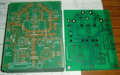
Really nice cards 🙂
This could be great fun when we all start to compare our different aproach to this build. Case, outside components etc.
I'm trembling like a child in excitement

This could be great fun when we all start to compare our different aproach to this build. Case, outside components etc.
I'm trembling like a child in excitement
OK, good news on the boards. The tooling is being reused and the remaining 30 are being made for the originally quoted price.

Radioman62 said:Really nice cards 🙂
This could be great fun when we all start to compare our different aproach to this build. Case, outside components etc.
I'm trembling like a child in excitement
I'm excited too 🙂
But I just returned from a ~600km solo return trip to service one of the states seismographs. Been flat out since 6:45am and was on here to about 11pm last night.
I don't feel like soldering now. I think I'll eat something and go to bed.

G.Kleinschmidt said:a ~600km solo return
I figured Mad Maccie would enjoy taking his V8 Interceptor for a bit of a stroll ?
How about some propaganda talks about running hybrid amps in bridged mode or building an active hybrid 3-way LSP to sucker a few more gents for the again remaining 20 PCBs.
jacco vermeulen said:
I figured Mad Maccie would enjoy taking his V8 Interceptor for a bit of a stroll ?
How about some propaganda talks about running hybrid amps in bridged mode or building an active hybrid 3-way LSP to sucker a few more gents for the again remaining 20 PCBs.
LOL, no, I used the work provided Nissan Patrol.
BTW, since you mentioned "V8 interceptor", I almost fell over a year or so ago while walking from the caravan park to the pub for dinner in a remote desert town I pass through every now and then. Standing in front of the Hotel under a tree, with four flat tyres and totally covered in dust, was a still rust free and straight, totally original Jensen Interceptor (with the big Hemi under the hood)

To the best of my knowledge it is still there. According to a local it belongs to the towns mechanic and has been sitting under the tree untouched for years.

If only I had the space to put it and the spare cash to make the mechanic an offer.....
Good night
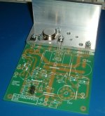
Progress report:
I had the opportunity to cut and drill the heatsink bracket this afternoon.
I used 6mm thick aluminium angle. I would have preferred to have mounted the PCB on one of these….
http://www.altronics.com.au/index.asp?area=item&id=H0538
6mm flanged heatsinks, but the supplier local to me was out of stock.
Anyway, tomorrow is Saturday and I will be able to spend most of the day working on it.
Cheers,
Glen
Attachments
- Status
- Not open for further replies.
- Home
- Amplifiers
- Solid State
- The Kleinschmidt 10A