Jelco are nice arms. 10.5” seems to be the sweet spot in arm length in general.
Arm choice (mass and resonances) forces cartridge choice and vise-versa. Are you interested in any particular cartridges? You may want to see if the arm will be a good match.
Arm choice (mass and resonances) forces cartridge choice and vise-versa. Are you interested in any particular cartridges? You may want to see if the arm will be a good match.
Yes. 9 inch is too short. You can make it work, but then it needs to be mounted fairly far forward. 12 inch has the exact opposite problem: it requires a large-ish plinth. Some folks don't seem to mind the latter, though.
9" works fine, though yes, it mounts a bit forward on the plinth. What I was getting at with 10.5" vs 12" is the increase in total mass and inertia is more of a disadvantage than the gain in geometric alignment.
Last edited:
Looks like the 10.5" will fit nicely symmetrically pleasing too, without looking to near or far away from the platter.
I m currently using Ortofon 2M blue and Nagaoka MP150, will these match well with the 10.5" ?
Alternatively, is there any good cart that work well with this 10.5' ?
This is getting exciting.... 40 yrs old T/T refurbished and going to generate some music !
I m currently using Ortofon 2M blue and Nagaoka MP150, will these match well with the 10.5" ?
Alternatively, is there any good cart that work well with this 10.5' ?
This is getting exciting.... 40 yrs old T/T refurbished and going to generate some music !
I have four MkII with the brake mechanical assembly completely removed but the solenoid left in place to avoid cutting wires. As you mentioned, there is momentary reverse drive that slows the platter and it then gradually slows down. Removing the brake assembly allows the motor to be directly bolted to the machined face of the chassis without the intermediate plastic ring. This allows better integrity of the motor/chassis coupling. You will hear the solenoid click when the stop button is pressed but it does no harm. The mod is completely reversible.Maybe I'm just confused or haven't been paying attention. It was my understanding that a fair number of people remove the break band for whatever audiophile reasons, yet I've never heard reports that these people had reversing platters when they hit 'stop'. It was my impression that the platter would just slow down and stop like most other turntables.
Another advantage of disabling the brake is if you use a peripheral ring as I do. The sharp stopping of the platter can cause the ring to slip through inertia. The contact region of the ring is only a tiny lip of the LP with very little friction.
The journey begins...
For a while now I've been intrigued by the classic high torque direct
drive turntable. However, I had never considered putting together
an SP-10 table, believing it to be more complicated than I can
handle.
However, some encouraging words from Rayma ("It's much easier than building an amplifier, and it won't blow up on you")
and 6L6 ("Taking on an SP-10 project is not as difficult as it seems. All the pieces are available, just separately.")
led me to seriously consider this.
Then as luck would have it, I stumbled upon a 'local' SP-10 Mk2 for sale.
After some communication with Jim, I took a leap of faith.
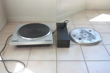
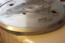
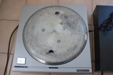
The mat is quite worn and the platter has a fair bit of corrosion. The
seller threw in a spare platter which was in pretty rough shape. However,
after a bit of wet sanding, the edge is looking not too bad and actually
better than the 'good' one.
I think this is going to be a lot of fun.
Cheers,
Dennis
For a while now I've been intrigued by the classic high torque direct
drive turntable. However, I had never considered putting together
an SP-10 table, believing it to be more complicated than I can
handle.
However, some encouraging words from Rayma ("It's much easier than building an amplifier, and it won't blow up on you")
and 6L6 ("Taking on an SP-10 project is not as difficult as it seems. All the pieces are available, just separately.")
led me to seriously consider this.
Then as luck would have it, I stumbled upon a 'local' SP-10 Mk2 for sale.
After some communication with Jim, I took a leap of faith.
The mat is quite worn and the platter has a fair bit of corrosion. The
seller threw in a spare platter which was in pretty rough shape. However,
after a bit of wet sanding, the edge is looking not too bad and actually
better than the 'good' one.
I think this is going to be a lot of fun.
Cheers,
Dennis
Attachments

Looking to remove the SH10C from my set up.
It doesn’t do any harm, but it’s redundant and takes up space.
Anyone able to help? Without a complicated lesson? If it’s hard work I’ll leave it...
Second thing is my SH10e power supply orange pilot light isn’t working.
Which part do I replace it with?
Thanks to anyone who can help.
It doesn’t do any harm, but it’s redundant and takes up space.
Anyone able to help? Without a complicated lesson? If it’s hard work I’ll leave it...
Second thing is my SH10e power supply orange pilot light isn’t working.
Which part do I replace it with?
Thanks to anyone who can help.
My SP10 Mk2 came without the SH10C, it had the cable for it, and the 'timing dots' on the chassis, so I assume it was a 'broadcast' model of some sort. I was also lucky that it had the Start and Speed switches still wired up. but not functional. It took a bit of fiddling and a small additional circuit board, but was quite straightforward in the end.
I think we need a bit more info about your machine before accurate recommendations can be made. What version is it? (on back of chassis), pictures of the internals, and especially the circuit boards would be very helpful indeed.
The bottom line is that there are enough skilled members here to hopefully give you all the advice you need.
One other thing...
Anyone know the power consumption of the SP10 and SH10e psu when on, and off?
Planning on hiding my psu away and interested in power draw in both switch states of the psu.
Anyone know the power consumption of the SP10 and SH10e psu when on, and off?
Planning on hiding my psu away and interested in power draw in both switch states of the psu.
Ok
After some endless googling I found this on an Australian website, by chance
“soldering-in a standard 3.3V 3mm diameter low power LED of whatever colour.”
For the SH10 power led!
After some endless googling I found this on an Australian website, by chance
“soldering-in a standard 3.3V 3mm diameter low power LED of whatever colour.”
For the SH10 power led!
The power supply doesn't draw any current (bar any leakage through the switch capacitors)when it is switched off, the switch is on the primary side of the mains transformer.
Making the stop start switch work internally requires a deft hand with a soldering iron and I went through this in detail a few pages back covering the BBC rp2/9 Sp10 mkii P.
If I had a SH10C i'd keep it and wire the original turntable stop start switch in the position indicated on the circuit digram across pins 2 and 8, you can pick up the s/s start switch via the logic board and a with few small wiring changes it could be made to operate via the SS/SS wires. Its hard to know for sure without actually knowing internally what version you have of the logic board.
How do you stop and start it currently?
Download the circuits for the SP-10 and SH10C from Vinyl Engine , it should be possible to replicate the start/stop on the original PCB, but they did vary, so a photo of that PCB would be good.
In desperation you could dead-bug a flip/flop on the edge connector ? I'm not proud of that one, but it worked !
Dave
In desperation you could dead-bug a flip/flop on the edge connector ? I'm not proud of that one, but it worked !
Dave
I start and stop it exactly as usual: with the deck switch.
I just HAVE to include the SH10C as an extra box in the link.
If I remove it and use just the SH10E the deck lights up but the on off switch is useless!
The motor unit has two hard wires coming out the back and no sockets.
One power lead to the SH10C and one grey cable with a monitor type socket that also goes to the 10C.
Last edited:
It will be useless as the multipin connector carries all the control signals. As Dave mentioned, open it up and post some photos. All the answers are to hand once you look at the circuit diagrams of your particular model. Until you know what model it is and what version of the logic board you have, its all speculation.
Vinyl Engine has all the various manuals listed, covering the range of models. I suspect the manual for yours is Sp10Mkii P/L (BBC). I've downloaded it and it has a nice circuit diagram of the SH10C inside.
Vinyl Engine has all the various manuals listed, covering the range of models. I suspect the manual for yours is Sp10Mkii P/L (BBC). I've downloaded it and it has a nice circuit diagram of the SH10C inside.
It is 100% the BBC version.
Thanks for the comments.
Although I have no idea what to do! I’m not that inclined to open it up just yet. I suspect I will just live with the extra box for now until I find someone who can open it up and knows what to do!
Is it usual the psu gets quite warm ?
Thanks for the comments.
Although I have no idea what to do! I’m not that inclined to open it up just yet. I suspect I will just live with the extra box for now until I find someone who can open it up and knows what to do!
Is it usual the psu gets quite warm ?
For some reason I can’t edit posts...
So quick update is that my model is the SP10 m2 P/L BBC version. It’s clear from the sticker on the deck.
I have found the SH10C diagram as you mentioned. Problem is I don’t understand it!
Apart from allowing the start and stop functions to be wired remotely, does this box do (or add) anything else?
If anyone can explain what it does I’d appreciate it. (I have decided to just leave it there as I suspect the hassle of modifying it to remove it outweighs the benefit of just ending up with the same result minus one box!).
I suspect it must do something beyond allowing a remote start switch?!
i can’t post direct links to the website...
If you can access the sp10 page on vinyl engine, it’s the 7th document up from the bottom in the list of manuals
Page 11.
MiiP/L manual posted by abtsound
If you can access the sp10 page on vinyl engine, it’s the 7th document up from the bottom in the list of manuals
Page 11.
MiiP/L manual posted by abtsound
Last edited:
OK, page 11 you need to put the top left hand circuit with the de-bounce and flip-flop onto you turntable. You need to see by downloading an ordinary manual if these parts are on your main PCB inside the turntable as they are almost certainly missing altogether. As I said, a photo of that PCB would help.
Dave
Dave
- Home
- Source & Line
- Analogue Source
- The Incredible Technics SP-10 Thread