It sounds like you may be conflating power supply and motor control electronics?
The video is rather vague, but the way it was described sounds far more like he "outsourced" the motor and control to his chassis, used an external LPS, and put the start/stop and speed buttons in his power supply chassis.
People have been doing this for quite some time - nothing new about it, and I'm not sure what makes it a Kanetasan variant, as the Kaneda designs, while having a bit of an evolution, were rather specific.
Regardless, "because LPS" is rather meaningless today when we've switching implementations that can outclass an LPS. For the rest, I remain firmly in the camp of "show me repeatable objective evidence of audible improvement".
BTW, as you brought it up, I recall reading that he studied audio engineering, but didn't see any indication of an EE degree or background. Can you drop him a line on the pronunciation of Garrard? 🙂
Last edited:
I'm not an EE but do have more involvement with mechanical concerns relating to TT's, I have always been fortunate to have adequate EE support when required, as well as, at times be steered by those with much better mechanical knowledge than my own.
My first experience of a TT's Platter Bearing undergoing a upgrade treatment in place of the manufacturers version has been over 25 years ago on a Idler Drive TT.
Measurements were not required at this time or any other time since to show why a change made to a mechanical interface has been for the better or worse.
Changes to mechanical interfaces have for myself, been able to present a detectable change, in nearly all cases one that is audible, a change that is effecting the voicing of the sound being produced, usually, one that allow more of the sound to be presented with a perceivable less loss.
When working with the Lenco TT's, a PTP Chassis version of a Lenco, does have significant improvements where the end voicing for the produced sound is concerned, especially when compared to a typical design for the chassis mounted bearing and motor.
A modified typical chassis on a Lenco, the type that has the typical chassis cut to produce the circumference pressing of the chassis form only, and then interfenece fit pressing the chassis circumference form into a rebate on a Plinth, is as a modification very closely resembling the PTP version of the Lenco.
Differentiating these two methods is not as easy as differentiating the sound being produced from the typical chassis design.
Measurements have not been required to reinforce the notion differences are detectable
Experiencing Work that has been undertaken with the Bearing Housing on a selection of different drive TT's, has also produced assemblies with alternate materials in use to the original, that have had very impressive impact on the sound being produced. For myself no measurements have been required to be taken to reinforce what has been detected as a valuable audible presence.
Changing materials used for the Plinths on a TT, as a result of my experiences of doing this, has also produced quite noticeable changes to the voicing of the sound being produced.
I have not used measurements to reinforce my experiences, but have seen measurements for a variety of materials that show some of my choices for a material will be a superior option.
I have for many years, pretty much since first discovering the Dr Kaneta design for the SP10 MkII, viewed the PTP and Kaneta and later Variants discovered as a similarity in design concept, being not too far apart in their design intent.
As a mechanical interface the SP10 MkII and now seen 1200G Spindles Bearing Housing and Motor, will in my assessment as a result of past experiences, benefit from being removed from the original chassis, where the new fitting to the support structure will be a low friction interference fit, with the TT's metal casting contained / bedded into a accurately dimensioned rebated material functioning as the chassis / plinth.
This method, will in my view, has potential to add to the quality of the sound being produced, and create a voicing that has a further attraction. There are other designers selling commercial products for substantial monies, having adopted similar mounting methodologies.
I can't see how a measurement of such a set up will reinforce my assessment of the sound being produced.
I am always keen to learn where a Electrical Improvement can be found as a betterment, I have access to individuals who are quire happy to discuss the concepts put on the table, hence my introducing the 1200G with an alternative mounting and Power Supply to these individuals as well as the forum.
There's over a centuries worth of research on perception and bias, and practically anyone who has performed sensory testing with appropriate controls fully understands just how proficient our brains are at lying to us. Evidence of audibility is not exclusive to measurements, and today is extraordinarily easy to do. Evidence of objective improvement can be a bit more difficult, particularly with analog sources, but that need not be the first bridge to cross.
I don't understand all this well but I ask you if does anyone have any instructions or a link to view a tutorial if one is to add a bearing drainon how and with what to drain the bearing in an SP10 II?
Albert Porter is a name historically associated with the term Bearing Drain, especially on the SP10 MkII.
His follow up work is still seen as a recommendation to other SP10 owners.
I know from previous experiences, rigidly securing the Bearing Housings projecting Shaft is beneficial, the reduction in flexion is worthwhile achieving.
If a drain rod is added to a design there may be a little more to be achieved.
The original drain rod designs will have contributed to adding a increased proportion of rigidity to the bearing housing.
Google: albert porter audio SP-19
many thanks, I started searching on the web but many photos are no longer visible, it is not possible to understand for example (by not making the photos visible) whether the unloading of the bearing must be carried out with the cap in the engine inserted or removed completely; Does anyone have any guidance on this particular detail?
Attachments

The cap MUST be in place or the ball could move, also possible for oil to leak.
The simplest method is to install a large bolt in the plinth and screw the bolt against the bottom of the bearing cap then lock it in place with a nut.
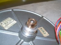
My solution is to use a locking ring. The bearing cap is tapered and opens the ring against the plinth locking the bearing against the plinth. This solution can only be implemented where the motor is removed from the SP10 chassis.
Photo of the bearing collar and installed motor


The simplest method is to install a large bolt in the plinth and screw the bolt against the bottom of the bearing cap then lock it in place with a nut.
My solution is to use a locking ring. The bearing cap is tapered and opens the ring against the plinth locking the bearing against the plinth. This solution can only be implemented where the motor is removed from the SP10 chassis.
Photo of the bearing collar and installed motor

@warrjon
Thanks for the suggestions, very interesting.
Surely your solution is more elaborate, but I assume that Porter's solution can also bring benefits.
Can you tell me if instrumental measurements have been carried out in the past to evaluate whether the bar for discharging the vibrations of the bearing actually works or was everything evaluated by ear?
I have have never performed in isolation measurements of the captive bearing. I suspect it would be difficult to quantify. For me it's just sound engineering to ensure the bearing is as rigid as possible and there is a path for the energy to flow.
If you place a contact microphone or stethoscope on the bottom of the bearing while playing an LP the music can be clearly heard, connecting the bearing to the plinth will provide a path for this energy to escape the bearing. Without this path 90% of the energy will reflect back up the bearing. This is exactly the same phenomenon as energy reflection from a tonearm CW and stub, this gets a lot of discussion but a bearing does not.
How audible this becomes will depend on many other variables. If the system is not revealing ie it's warm (high distortion) then it may be inaudible. A ridiculous example of this is play a $1,000,000 TechDas AF Zero and a cheap $50 TT through a set of earbud headphones and will you hear the difference.
Not really difficult to ascertain audibility of playback with before and after laybacks and some reasonable controls, and transparent electronics are ridiculously plentiful. Hand waving is more fun, though.
If one wants to see methods used to rigidly secure the Base of the Bearing Housing, there are various versions of methodology to be seen as a result of trawling through the Lenco Heaven Forum.
If one really wanted to make a design, with the main intention to work as a drain, there is a design that could be adopted where the Screw Cap on the Bearing Housing Base is exchanged for a oversized Cap machined from Brass.
The Brass Cap could be drilled/tapped to receive a Brass Threaded Rod.
The Top Face of the Brass Rod could be rebated to a dimension that enables a Bespoke Produced Thrust Pad to be inserted.
Different Materials could be selected to fine tune the voicing, resulting from this mechanical interface.
The Drain Rod could be attached to an Substantial Anchor Base produced to a Bespoke Size. The Anchor Base could be produced from a Metal, Cast Iron, Thermoplastic or Densified Wood. The Anchor Base can also be produced with a rebated Top Face, to allow for other substances to be considered for use in conjunction and safely contained. The intention for other substances is to have options to add a further voicing by being able to add a range of control for the the damping/dissipation of Bearing Housing Transferred Energy.
Substances to be considered can be Newplast Modellers Putty, Lead Shot, Oil Compacted Sand, or even a Silicone Oil.
The result of the above should be that a mechanical interface is in place that enables Bearing Housing produced energies to transfer through a path to a place of damping/dissipation. This path for energy transfer is successful in damping/dissipation will reduce the energy transfer that the Platter typically receives. The overall result being the Styli will not have as much non-modulation energy received.
The oversized Cap on the base of the bearing housing as a result of flexion being at its maximum at this point, can also have a counter measure side force applied via a arrangement of Three Horizontally Set Bolts.
Depending on the rigidity of the anchor point for the horizontal set bolts, the intention for the applied side force is to rigidly secure the Base of the Bearing Housing, as the oversized Cap will be a Pendulum and the flexion with added weight can easily manifest as a Ellipse Pendulum Rotation, ultimately increase off axis rotation for the Spindle.
This is almost the same as a design I shared with another for use on their Sony TTS 8000.
The user report returned on this as method for the Sony were very very positive, especially when used in conjunction with the design changes for the Sony's internals of the bearing housing and the realised modifications that had been carried out.
So, it's my turn to refurbish the SP-10...
While the chassis is out for repaint, where to start? Check/change the electrolytic caps?
Thanks in advance

While the chassis is out for repaint, where to start? Check/change the electrolytic caps?
Thanks in advance
Replace the electrolytics in both the PSU and turntable, replace the bearing thrust pad, and that’s about it, these things are tanks.
You are going to love it!!
You are going to love it!!
Be sure to align it according to the service manual after replacing the caps. Alsi nore that the orange electrolytics are low leakage types. Many/most modern caps meet this spec but i use nichicon UKL series. Just my 2 cents worth.
If by 'orange electrolytics' you mean the orange capacitors in the picture above from peppennino, those are NOT electrolytic capacitors. They are (Panasonic, probably) film capacitors, and should not need replacement.
He means these orange/yellow electrolytic that were designated low ESR. SP-10MK2A and MK3 have them, but the MKII does not.
- Home
- Source & Line
- Analogue Source
- The Incredible Technics SP-10 Thread