Love creating hifi equipment
Joined 2023
Paid Member
I have a couple of gimbal motors that are very quiet. They are big and not cheap ($300+). And my Anaheim motor for my belt drive is dead silent, but likely too tall for a direct drive setup. The Anaheim runs well in belt drive as it is mostly unloaded. The gimbals in my direct drive experiment will be loaded with 5lbs+ of platter. I have some more work to do there getting down to TechnicsSP10 levels of speed precision at a constant 33.33rpms, tho. I am getting about 0.12% speed variation which is not yet good enough.
The Technics SP-10mk2 motor seems like a very good no cogging PMSM. Definitely a bargain. And it could be driven easily by the SimpleFOC stack above if you want to experiment with FOC communtation. Just an option.
For me running the mk2 motor with FOC is last 1% in my attempt to improve the mk2 so using a gimbal motor is not something I would consider. Very quiet is not good enough the motor needs to be totally silent when the motor is spun with a stethoscope on the platter.
I already have the C code written to run the SP10mk2 motor with FOC using an STM32 and a DRV8301. My goal is 10 times better speed stability than the stock mk2 so 25ppm dynamic,. 250ppm would be a failure for me as it's the specification for the stock SP10, 0.025%.
Is your 1200ppm dynamic or static? Does the gimbal motor have ball race bearing? if so you might find the bearings are the weak point in improving speed stability. Keep in mind 0.12% speed stability is very good for most application a gimbal motor would be used for. How are you measuring the 0.12%.
0.025% is the JIS specification, and that specification includes a test record, arm, and cartridge which puts a rather high floor on the measurement. You'll need to baseline it with a method that doesn't have such an artificially high floor.
I had some unanticipated forced downtime that afforded me the window to write the script to facilitate these measurements and plots. These are laser displacement measurements of a MKII platter, taken from about 1cm in from the platter lip, spinning under its own power. This is an early unit that I imported from Japan 2-3 years ago. It shows signs of being stored in a slightly unfavorable environment. The motor is untouched.
The max deviation is 0.07623mm / 0.0030" over four revolutions. It's 0.09152mm / 0.00360" over 200 revolutions. Time permitting I'll measure it with a cartridge on a cut-down record, and repeat all measurement after servicing the motor. And, of course, measure a few more units.
For giggles, the second plot superimposes four revolutions of what I'd consider a rather flat record. Max deviation is 0.33559mm / 0.01321". Platter and record measurement are not indexed.

JP, sorry about the down time but that is interesting as heck. A couple of questions, neither of which are questioning what you did.
First, if we looked down at the curves directly from the top (I would normally call it the Z axis) would the curves be circular without most of the deviation.
Second, if not, can you show it. Or if yes, is there a way to measure it.
Given the size of the information in the groove, It amazes me the sound is as good as it is.
Thanks,
Don
This is only displacement data to measure runout, so the Z axis has the only data. X and Y form a mathematical circle as a 3D projection was easier to interpret than 2D.
EDIT - and question anything you like - no issues.
EDIT - and question anything you like - no issues.
Last edited:
Would it therefore be fair to say that as the record (a good one) is around 5 times greater than the platter then the platter "problems" are relatively irrelevant?
I'm not comfortable with making a sweeping generalization based on how a single unit measures, though I don't really see anything here that wasn't expected. Actually, I thought the overall runout of the platter would be higher. I still want to see it with a cartridge tracking at ~2g, though I don't think that'd make any difference. I've been surprised before, so would want to be thorough.
I can say for how this unit measures under these conditions, platter "problems" appear to be non-existent.
I can say for how this unit measures under these conditions, platter "problems" appear to be non-existent.
Runout is not an issue in SP10 platters, one of the worst I've seen was on the lathe last week and it had 0.27mm TIR at the outer edge of the platter, this excludes precession in the bearing as the platter was fixed to a faceplate with less than 0.005mm TIR, Turning the platter over and indicating on the motor mounting face showed 0.03mm TIR in the mounting face. The mounting face was skimmed to true it up.
Slow runout in a platter will not cause cantilever deflection. If runout it's very large it will cause azimuth tilt, but this is a separate issue and not one that is present in any of the SP10 platters I have tested. The issue is the fast pulsing seen on a DTI caused by bearing clearance. This fast pulsing will cause stylus deflection and generate an unwanted signal. This is a well known phenomena in regular TT bearings made worse with small diameter journals. Linn went to great lengths to close up the journal to sleeve clearance using PEEK in order to reduce this effect, other manufacturers have converted to inverted bearings.
You need to measure the instantaneous deflection of the platter. Averaging the measurement will mask these fluctuations.
What are the temporal and axial resolutions of the measurement, How are you calibrating the sensor. How are correcting for incident angle? and what is your uncertainty. If you quantify these and develop corrections this could provide a better picture than a DTI.
512us sampling w/ no averaging applied, 1um repeatability, 30um spot. I'm squaring the head to the platter which is plenty good for the minuscule effect to the span accuracy an error within that will have.
Surface noise is an issue. The above plot data had a 10Hz LPF applied for readability. Below is unfiltered with a ~1mm wide piece of tape on the platter, which is the blip at ~1.1s. So far I've yet to see anything that indicates a pulsing movement of the platter.
Getting a more friendly surface for the platter would be high on the list. I may also have a system inbound with 2.5us sampling. This isn't the intended application, but I can add it to the winter project list. I would like to see some evidence of this problem existing, and to a degree that audibly affects playback, before going too far down a rabbit hole.
That's a better representation and easy to see the precession of the bearing. 4 or 5 rotations with the same graph would be interesting.
If this was purely runout you would expect a transition from low to high back to low in 1 revolution RED line. If we assume the noise is normal distribution and the measurement is approximately in the center Black line it's clear there are 2 high and 2 low spots in 1 rotation of the platter, with the second high spot greater in amplitude and Q. Either the platter is warped or there is precession in the bearing. This closely resembles what is seen on the DTI.

If this was purely runout you would expect a transition from low to high back to low in 1 revolution RED line. If we assume the noise is normal distribution and the measurement is approximately in the center Black line it's clear there are 2 high and 2 low spots in 1 rotation of the platter, with the second high spot greater in amplitude and Q. Either the platter is warped or there is precession in the bearing. This closely resembles what is seen on the DTI.
The first plot I posted is four consecutive revolutions, and the precession is clearly shown. Being a slow, once per revolution movement, it is of no consequence.
hello
i receive a defect EPA-100 recently,
and trying to repair it by myself.
after disassembly,
i repair the anti skating.
the only problem left seems to be the bearing,
my tonearm works not so smoothly in vertical.
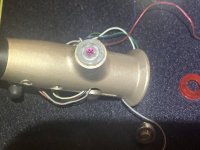
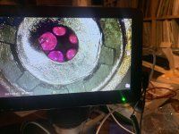
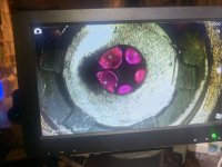
and after disassembly, a ruby of bearing on one side of tonearm tube is cracked
but i need help now
how to remove the cover of bearing?
i've bought the SiN3 balls instead.
but it seems no way to remove the cover without breaking it?
thx for any help!
i receive a defect EPA-100 recently,
and trying to repair it by myself.
after disassembly,
i repair the anti skating.
the only problem left seems to be the bearing,
my tonearm works not so smoothly in vertical.
and after disassembly, a ruby of bearing on one side of tonearm tube is cracked
but i need help now
how to remove the cover of bearing?
i've bought the SiN3 balls instead.
but it seems no way to remove the cover without breaking it?
thx for any help!
Attachments
It can’t be removed. You have to bend it up enough to get a ball in/out at a time and then bend it back.
hello JP
thank you for reply.
what kind of tool you use?
as the photo one of cover is damaged
i try to use a needle to fix it but useless
thank you so much!
thank you for reply.
what kind of tool you use?
as the photo one of cover is damaged
i try to use a needle to fix it but useless
thank you so much!
I made my own. I usually start with small hardened flat head screwdrivers and re-shape them to do what I need.
Here is an SP10 remote motor in a Permalli plinth I built for a friend

Lucky friend! - which version of remote motor is that please? - remote as in 2 platters below the vinyl?
The motor is removed from the SP10 chassis and installed in a separate plinth. This removes an enormous source of erroneous vibration. To facilitate this an umbilical cord is made to connect the SP10 electronics to the remote motor.
The stock platter has 30mm POM fixed to the top and a decoupled spindle.
The stock platter has 30mm POM fixed to the top and a decoupled spindle.
- Home
- Source & Line
- Analogue Source
- The Incredible Technics SP-10 Thread