My bad I just looked at the cct and you're correct. I did ask him to check for 32V at the solenoid.
Hi, Sorry not replied sooner, been down with the dreaded flu!!
Checks for ripple just now & 69 VDC recorded on orig 24 VAC trans & second 36VCD SMPS was even higher, So I am amazed it even works a all.
My P/S is obviously not doing it's job, however in case my line voltage was way over (could not measure on my meter) I went through a 110 converter with the SMPS & that recorded an input of 132VAC!!. But my output voltage checked out a 32VDC, however did not improve the ripple.
Luckily in the post I received the other day a P/S board specifically made for the SP10 mkII. It was donated by another kind member on the A/K forum. I thought it had been lost in the post as it was posted 4 months ago. (that's why I started playing around with my piece meal version)
So I guess I need to hold my horses & get the new P/S made up & then just tray again.
Cheers for your help, knowing my luck I will need to send the boards to you if that is still OK.
But for the short time had the T/T working I certainly know it is well worth the effort & the sound improvement over my SP15 was gob smacking.
Cheers again

@DNic Do you mean 69mVAC (0.069V) as 69V is more than the 24VAC. Even 69mV is high, on the TT's I've serviced AC ripple is under 10mV.
Did you check the 32V at the TT or only at the PS. With an unkown PS I always check/adjust voltages with the TT disconnected then connect TT and measure voltages at the TT as there could be connection problems that will not show if you check at the PS.
Did you check the 32V at the TT or only at the PS. With an unkown PS I always check/adjust voltages with the TT disconnected then connect TT and measure voltages at the TT as there could be connection problems that will not show if you check at the PS.
Hi, yes sorry My Bad, So Now I just have to order parts for the new P/S board, which I will do later today.
Cheers
Cheers
The ripple sensitivity is on the 5V rail, though I've never tested the threshold on the 32V rail. As all the logic is on the 5V rail it still seems the brake solenoid would energize regardless. But as you say, probably best to start with a known quantity now that you've the boards.
The good news is almost everything that'd need to be troubleshot to get the platter to move can be done with a meter. If there's an issue from there you'd need a scope.
Here's to hoping it'll work fine on the new PSU out of the gate.
The good news is almost everything that'd need to be troubleshot to get the platter to move can be done with a meter. If there's an issue from there you'd need a scope.
Here's to hoping it'll work fine on the new PSU out of the gate.
Hi, Sorry, Just seen this. On my unit the 33 RPM LED light comes on when the 5VDC is connected & the 32VDC is not switched on (it has a separate switch)?
Cheers
Cheers
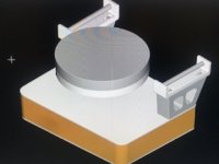
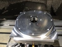
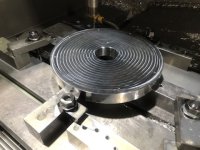
I was approached recently to build 2 more inverted bearing SP10's complete with linear tracking tonearms. The PCB's will be removed from the SP10 chassis and housed is a custom enclosure. To increase motor rigidity the OEM motor housing is being deleted and a custom billet stator and rotor housings will be machined. The ground plane (plinth) will be increased in thickness to around 100mm.
Here is the concept CAD drawing and the pics of the platters being CNCed. I'll post more pics during the build process.
Here is the concept CAD drawing and the pics of the platters being CNCed. I'll post more pics during the build process.
Attachments
Warren, could you kindly remind me of the fundamental benefits of the inverted bearing, perhaps with a diagram?
Best
Mike
Best
Mike
A regular TT bearing has the rotation point at the bottom of the spindle well below the COG of the platter. Try standing this on a table it will fall over. The only thing preventing it from falling over is the journal sleeve which in the SP10mk2 is small in diameter (9/32). This small diameter and slow speed 78rpm (max) does not provide fast enough velocity to create oil swirl for proper hydrodynamic oil pressure so the spindle will wobble in the sleeve. This minute wobble is multiplied by the radius of the platter and is chaotic in nature. This chaotic wobble will cause the cartridge to output an unwanted signal.
A platter sitting on an inverted bearing where the point of rotation is slightly above the COG will rotate with high stability.
Here is an article by Pierre Lurne that goes into the advantages and include a diagram.
https://www.tnt-audio.com/sorgenti/belladonna2_e.html
A platter sitting on an inverted bearing where the point of rotation is slightly above the COG will rotate with high stability.
Here is an article by Pierre Lurne that goes into the advantages and include a diagram.
https://www.tnt-audio.com/sorgenti/belladonna2_e.html
Fascinating Link, needs hours of reading.................
M
but at least i now understand the basics!
M
but at least i now understand the basics!
That is so cool. Getting hard to make the MK2 any better than thatI was approached recently to build 2 more inverted bearing SP10's complete with linear tracking tonearms. The PCB's will be removed from the SP10 chassis and housed is a custom enclosure. To increase motor rigidity the OEM motor housing is being deleted and a custom billet stator and rotor housings will be machined. The ground plane (plinth) will be increased in thickness to around 100mm.
Here is the concept CAD drawing and the pics of the platters being CNCed. I'll post more pics during the build process.
@donhughes111, the main reason for the update is to make the TT look better, radius's on the corners and a curved front. The new motor housing will significantly increase rigidity in the motor. This will reduce flex in the journal shaft as the platter spins as well as a more direct path to the plinth for motor vibrations. Oh and the journal will be a custom ground solid carbide shaft.
There is a final update in development, which is vector control for the motor via a micro controller. I guess at this point it's no longer an SP10.
There is a final update in development, which is vector control for the motor via a micro controller. I guess at this point it's no longer an SP10.
Denon's new DP-3000NE turntable has, per an audiophile website, "Space vector pulse with modulation (SV-PWM)” algorithm", whatever that is. I think they mean 'width', not 'with'. Sounds pretty fancy.
SVPWM is the FOC modulation type. So they are using a micro-controller and FOC to drive the motor. The benefit of this type of control is it's capable of maintaining 90deg vector of Id and Iq which are the direct and quadrature currents so you get max torque/amp and very smooth rotation.
Space Vector modulation adds a triangle wave to the sine wave on each motor phase. You get a slightly longer top to the waveform. For some BLDC motors, this is smoother.
For $40, anyone can play with FOC motor control with a low-ish speed 3 Phase motor. All you need is a $20 microcontroller like an Arduino or similar (I prefer the STM32 Nucleo boards), a $20 motor controller like the SimpleFOCShield2, and the SimpleFOC open source software. I am using it with a BLDC motor from Anaheim Automation to drive my belt-driven table with very good control. I am now experimenting with gimbal motors (meant for camera steadycams and panning) to get to a super-smooth direct drive.
SimpleFOC supports both SineWave and SpaceVector Field Oriented Control, so you can decide which is better for your motor and setup.
Does that last post concerning the gimbal motors indicate there might be a route to an inexpensive good direct drive motor to use on a home built TT?
M
M
Mike, I don't think gimbal motors are the best to use for a DD TT, A DD TT motor needs to rotate silently. Cheap gimbal motors will most likely use ball race bearings and all the ones I have look at do not specify if BEMF is sinusoidal or trapezoidal. This is why I decided on the SP10mk2 motor, it's high torque, silent running PMSP ie sinusoidal BEMF and we know it's capable of at least 250ppm speed stability.
The Thingap motor used by VPI is in the order of $4000US for the stator and magnet, makes the SP10 motor a bargain.
The Thingap motor used by VPI is in the order of $4000US for the stator and magnet, makes the SP10 motor a bargain.
Sounds like the Victor 81 is staying then!
Out of interest, which of the SP10 mk2 specs would the 81 meet, or maybe i dont wish to know that...........?
M
Out of interest, which of the SP10 mk2 specs would the 81 meet, or maybe i dont wish to know that...........?
M
I've had a TT71 and there was nothing between it and a stock SP10mk2. Where the gains are is adding POM to the platter and remote mounting the motor, both of these significantly improve the stock SP10, it would be similar for the 81.
I have a couple of gimbal motors that are very quiet. They are big and not cheap ($300+). And my Anaheim motor for my belt drive is dead silent, but likely too tall for a direct drive setup. The Anaheim runs well in belt drive as it is mostly unloaded. The gimbals in my direct drive experiment will be loaded with 5lbs+ of platter. I have some more work to do there getting down to TechnicsSP10 levels of speed precision at a constant 33.33rpms, tho. I am getting about 0.12% speed variation which is not yet good enough.Mike, I don't think gimbal motors are the best to use for a DD TT, A DD TT motor needs to rotate silently. Cheap gimbal motors will most likely use ball race bearings and all the ones I have look at do not specify if BEMF is sinusoidal or trapezoidal. This is why I decided on the SP10mk2 motor, it's high torque, silent running PMSP ie sinusoidal BEMF and we know it's capable of at least 250ppm speed stability.
The Thingap motor used by VPI is in the order of $4000US for the stator and magnet, makes the SP10 motor a bargain.
The Technics SP-10mk2 motor seems like a very good no cogging PMSM. Definitely a bargain. And it could be driven easily by the SimpleFOC stack above if you want to experiment with FOC communtation. Just an option.
- Home
- Source & Line
- Analogue Source
- The Incredible Technics SP-10 Thread