@Simon Templar
Were you able to compare the performance of the mk3 in your plinth with it mounted in the OEM Technics Non-Resonant Compound (TNRC) plinth?
If so, your opinion would be of interest to me and a few others. It might be better suited to The Incredible Technics SP-10 mk3 thread.
OTOH you might attract some undesired blowback, so I understand if you decline.
It might be better suited to The Incredible Technics SP-10 mk3 thread.
OTOH you might attract some undesired blowback, so I understand if you decline.
If opinions or subjective impressions are stated as fact actual evidence will be requested. If they’re not, then it won’t. It’s not a concept that most people have difficulty understanding.

I have had good results from JMK Displays. Fairly priced and high quality. I'm not affiliated. PM me for contact info if you can't find the website.I have a Mk3 in a custom plinth. The plinth is roughly of the same size and dimensions as most that one sees.
I am seeking a maker of the flat-type dust covers. Probably don't need anything custom-designed....I suspect any that fit the usual Mk3 plinth tables will suit me as well. Just need a quality source.
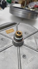
I've machined the new spindle from BS1407 tool steel. All that remains is to harden and polish the spindle, assemble the motor and change the motor connector.
@Simon Templar
Were you able to compare the performance of the mk3 in your plinth with it mounted in the OEM Technics Non-Resonant Compound (TNRC) plinth?
If so, your opinion would be of interest to me and a few others. It might be better suited to The Incredible Technics SP-10 mk3 thread.
OTOH you might attract some undesired blowback, so I understand if you decline.
Actually, no.
I've no experience with the OEM plinths
.....sT
That is gorgeous...Despite the fact that I thought you had used slate...Not that there is anything wrong with your solution but I had hoped to be able to copy your solutions for a lovely pies of slate that I have.
am I correct that 140v only used for the strobe light and if you are doing this led mod you can disconnect it on the PSU side?
his047: See detailed instructions for the cap removal under the Motor Refurb section of my first SP-10 refurb, here.
Basically, heat up the end cap with a heat gun and use water pump pliers. Then push a wood stick from the top and give it a tap to pop the bearing out - its a friction fit.
PKI: Correct, the 140V only powers the strobe bulb. In fact, when I build new power supplies for the SP-10 I completely omit the 140V supply.
Mike
Good point, will do!
While I am in the PSU what's the best way to replace that burned bulb in the psi with an LED, do I connect a diode in series or in parallel with the led? (also not sure if I need a resistor?) Thank you and my apologies if it was discussed here before.
While I am in the PSU what's the best way to replace that burned bulb in the psi with an LED, do I connect a diode in series or in parallel with the led? (also not sure if I need a resistor?) Thank you and my apologies if it was discussed here before.
If you use the same AC lines the bulb did then you'd want a series diode and resistor. With a 5mm orange LED I usually use something around 3k to get similar output as the bulb.
If you tap the 5VDC rail then just a series resistor in the realm of 150R-200R.
A 5mm LED will fit in the rubber mount for the bulb. It's a little snug getting it in there but works fine.
If you tap the 5VDC rail then just a series resistor in the realm of 150R-200R.
A 5mm LED will fit in the rubber mount for the bulb. It's a little snug getting it in there but works fine.
Hi, I have got a chance to pick up a SP10 mkII without P/S, 2 questions if I may.
Cheers
- what should I look out for on the unit
- is there a P/S kit available
Cheers
@DNic I also just picked up a mk2 with no PS. My plan is to build a new PS using a high quality SMPS. IME good quality SMPS are well shielded and low noise. The benefit is the noise is high frequency switching which is much easier to filter than mains.
If you can pull the bottom off look at all the PCB's for signs of repairs. I have seen a few that have come from broadcast environments where they have not been repaired very well.
Spin the motor and listen for noise. If you have another mk2 take your PS and run the TT.
It really comes down to the price they want for it.
Time Step @Dave Cawley sell an aftermarket PS. I think @mikebarney had a DIY PS on his website. It wouldn't be overly difficult to build a PS using cascaded LM317's.
Hi, Thanks for that, I have also just found this on Yahoo auctions
https://neokyo.com/en/product/yahoo/t1073480365
Cheers
https://neokyo.com/en/product/yahoo/t1073480365
Cheers
- Home
- Source & Line
- Analogue Source
- The Incredible Technics SP-10 Thread