Finally, I think I've dialled in my MK3. Thanks to @JP and @Dave Cawley for instructions and @hirscwi for the write up!
I do though experience a slight vibration when changing speeds. The offset voltage drops about 0.2-0.3V for a fraction of a second, the turntable looses sync on the scope and it vibrates before offset voltage is normalized and everything is fine again. The regulators feeding IC104 AN6562 is not fluctuating while changing speeds. Could it be IC104 being faulty? Something else I might have overlooked? Any feedback is highly appreciated!
I do though experience a slight vibration when changing speeds. The offset voltage drops about 0.2-0.3V for a fraction of a second, the turntable looses sync on the scope and it vibrates before offset voltage is normalized and everything is fine again. The regulators feeding IC104 AN6562 is not fluctuating while changing speeds. Could it be IC104 being faulty? Something else I might have overlooked? Any feedback is highly appreciated!
Last edited:

Hey, everybody!
Need some help. I am repairing SP10-MK3.
All modes recommended in the service manual are adjusted.
Speed capture is fast at all speeds.
But at 78 speed there is a sound from the engine.
This sound appears when there are current surges on the motor coils.
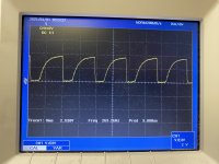
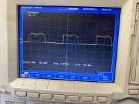
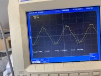
Oscillogram in collectors of output transistors at 33 and 45 speed is normal, but at 78 speed there are emissions and needles both on the upper and lower wave.
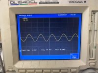
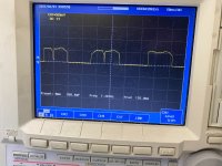
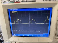
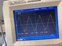
Also on the control outputs 1,2,3 of chip AN640 form of the control voltage has the correct form only at 33 speed.
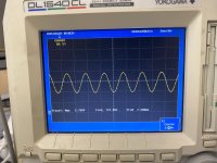
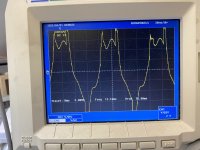
At 45 speed partially appear dips in the control pulses.
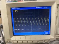
And at 78 speed the control pulses have a strong distortion and emissions.
Accordingly, the driver output transistors also produce artifacts on the control coils.
Capacitors of AH640 chip and output transistors are replaced.
Who ever faced with this problem?
Need some help. I am repairing SP10-MK3.
All modes recommended in the service manual are adjusted.
Speed capture is fast at all speeds.
But at 78 speed there is a sound from the engine.
This sound appears when there are current surges on the motor coils.
Oscillogram in collectors of output transistors at 33 and 45 speed is normal, but at 78 speed there are emissions and needles both on the upper and lower wave.
Also on the control outputs 1,2,3 of chip AN640 form of the control voltage has the correct form only at 33 speed.
At 45 speed partially appear dips in the control pulses.
And at 78 speed the control pulses have a strong distortion and emissions.
Accordingly, the driver output transistors also produce artifacts on the control coils.
Capacitors of AH640 chip and output transistors are replaced.
Who ever faced with this problem?
Pictures of the waveforms would help quite a lot.
Did you figure out the errors in the service manual for the adjustments?
This is a contradiction. If there's an issue in the pre-drive waveforms, there'll be an issue in the drive output waveform as well.
How fast? Have you determined where this is coming from? What's frequency of the output of the MN6042, and what is the frequency of the FG and how is the stability of the FG waveform?
All modes recommended in the service manual are adjusted.
Did you figure out the errors in the service manual for the adjustments?
Oscillogram in collectors of output transistors at 33 and 45 speed is normal
Also on the control outputs 1,2,3 of chip AN640 form of the control voltage has the correct form only at 33 speed.
At 45 speed partially appear dips in the control pulses.
This is a contradiction. If there's an issue in the pre-drive waveforms, there'll be an issue in the drive output waveform as well.
Speed capture is fast at all speeds.
How fast? Have you determined where this is coming from? What's frequency of the output of the MN6042, and what is the frequency of the FG and how is the stability of the FG waveform?
Hello JP.
Thanks a lot for the reply.
Yes, I know about the errors in the manual regarding the CN206 connector and what signals how to measure.
And other inaccuracies in the diagrams on the IC201 DN860.
But there is also a discrepancy in the circuits of chip IC101.
At 12nF indicated on the circuit of С110, the frequency of the oscillator is 33-34kHz.
In the manual of MK2 this capacitance is specified as 22nF, and on SR-15 this capacitance is specified as 5.6nF.
And with this capacitance of 5.6n the frequency of the generator is 50-51kHz.
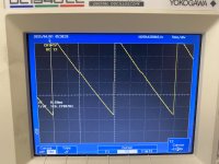
But now to the oscillograms as you asked.
File name - measurement point.
I hope you can make sense of my oscillograms.
I will be glad to receive any advice and help.
If you need additional information, I will provide it immediately.
Best regards.
Thanks a lot for the reply.
Yes, I know about the errors in the manual regarding the CN206 connector and what signals how to measure.
And other inaccuracies in the diagrams on the IC201 DN860.
But there is also a discrepancy in the circuits of chip IC101.
At 12nF indicated on the circuit of С110, the frequency of the oscillator is 33-34kHz.
In the manual of MK2 this capacitance is specified as 22nF, and on SR-15 this capacitance is specified as 5.6nF.
And with this capacitance of 5.6n the frequency of the generator is 50-51kHz.
But now to the oscillograms as you asked.
File name - measurement point.
I hope you can make sense of my oscillograms.
I will be glad to receive any advice and help.
If you need additional information, I will provide it immediately.
Best regards.
Attachments
-
 FI IC201 7.JPEG851.7 KB · Views: 25
 -
 FG 33 IC203 16.JPEG526.4 KB · Views: 27
 -
 FG 45 IC203 16.JPEG515.5 KB · Views: 28
 -
 FG 78 IC203 16.JPEG525.6 KB · Views: 28
 -
 33 ST2 CN206 4.JPEG459.6 KB · Views: 24
 -
 45 ST2 CN206 4.JPEG493.8 KB · Views: 25
 -
 78 ST2 CN206 4.JPEG537.6 KB · Views: 26
 -
 33 IC101 AN1.2.3.JPEG524.1 KB · Views: 27
 -
 45 IC101 AN1.2.3.JPEG546.3 KB · Views: 22
 -
 78 IC101 AN1.2.3.JPEG476.9 KB · Views: 26
 -
 33 A3 CN10 colector.JPEG577.8 KB · Views: 21
 -
 45 A3 CN10 colector.JPEG547.2 KB · Views: 28
 -
 78 A3 CN10 colector.JPEG561.2 KB · Views: 24
Interesting.
At a glance the drive waveform for all three speeds is abnormal, and gets worse as you progress through the speeds. It's handy if you've three scope channels to see how all three drive phases are interacting.
Not sure how accurate the hardware counter is in your scope, but IC201 FI should be 262.08kHz and FG at 33 should be 101.11Hz. However, drive frequency at 5.556Hz is correct.
I'd think from the drive waveforms that the notch in ST2 isn't stable? Can you record the FG signal from CN205? An audio ADC works fine though you'll likely need a series R on the input to not load down the FG circuit. 33 and 78 would be good.
12nF is the correct value for C110.
Motor bearing in good shape? Lubed with an ISO68 oil or similar?
I'll give the rest a think and try to come back tomorrow.
I was once foolishly inspired by the Garrard 301 and its grease bearing. However the Mk3 bearing has a quite large surface area and the stiction of grease or thick and/or old oil is not good and puts a significant drag/load on the motor. Hence John's recommendation of ISO68 hydraulic oil which is great quality and thin, is spot on.
BTW many, many years ago, I called the technical department of Castrol Oil and they recommended Hyspin AWS32 which is thinner than 68. And 'cos I bought 5L (a gallon) of it, I use it everywhere.
As usual YMMV
BTW many, many years ago, I called the technical department of Castrol Oil and they recommended Hyspin AWS32 which is thinner than 68. And 'cos I bought 5L (a gallon) of it, I use it everywhere.
As usual YMMV
Hello JP.
In the morning I started the repair, and took video oscillograms that you asked, I wanted to send them in the evening, but during the day I found the cause of this behavior of IC101 and output transistors. So the oscillograms are no longer relevant.
I disconnected IC101 driver chip from IC203 control and applied control voltage to IC101 5pin (ECR) from voltage source. The driver worked without speed stabilization, but there were no problems with the signals on AN1,2,3 outputs. The currents in the motor coils had an almost sinusoidal shape.
When analyzing the control voltage IC203 7pin - ECR (6.8-7.5V) in more detail, it turned out that there was sinusoidal modulation on the control signal.
At speed 33 the frequency was 28-35Hz and amplitude 30mV, and at speed 78 the frequency was 40-42Hz and amplitude 60-70mV.
I have not managed to find the source of this modulation yet, but if the ECR signal is additionally filtered with a capacitor, the modulation decreases and IC101 and output transistors work normally.
It remains to understand where the modulation with frequency 28-42Hz and amplitude 60-70mV comes from.
Here is the situation.
- Home
- Source & Line
- Analogue Source
- The Incredible Technics SP-10 MK3 Thread