I'm actually thinking that this idea has considerably more than a little merit, though I would probably replace the lamps with a CCS and suitable power resistor, but what a way to leverage inexpensive output transformers and repurpose off the shelf power toroids often employed with 6AS7G and the like.
Full SE operation, no or very little dc in the primary, inexpensive iron, and eliminating the need for gapped output transformers or a parafeed arrangement with choke, and fancy cap..
I think an amp based around a 6336/6C33/6080/6AS7G/6528 or similar with antek toroids for power and output would be an interesting project..
I am not sure where Ciro came up with this idea, but it is the first time I have encountered it, and so glaringly obvious that I now wonder why no one has used it before.. There is no reason why it could not work very well as far as I can see, and a good CCS with big series power resistor instead of the lamps will totally eliminate the AC loading imposed by the current canceling circuitry.
As long as voltage compliance requirements are met for the CCS at full output power it may also be possible to reduce the raw voltage used in the current canceling supply and improve efficiency to some degree that way. (Or you could make it switchable for low power and high power operation for a significant efficiency increase.)
The only downside I can see is that it does use appreciably more power than a comparable conventional SE amp, however in small amps this is not a big issue.
Last edited:
Ok, since my point about saving power by dissipating it was not understood and deleted by a moderator, I spent some time to explain it a little bit deeper.
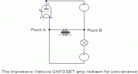
Here is redrawn for convenience of observation schematic added.
Actually, this is a SE amp. In order to compensate transformer bias an opposite current through it's primary is supplied by an additional PS and a lamp.
Without such a compensating current supply the amp would be a conventional SE amp (if to ground point A it is a common cathode amp, if to ground point B it is a cathode follower amp). And it's efficiency would be the same as of a conventional SE amp. But a lamp that is used as a ballast resistor consumes additional power. That means, it's efficiency is more than twice worse than efficiency of a conventional SE amp.
Power efficiency claimed in the item description is a sad mistake (I hope so!)
Attachments
Hello Ciro,
Thanks for joining this discussion and bearing with us.
Please excuse my earlier sarcasm, and understand that on face value your claims in the attached ebay listing do not hang together. Is a light bulb any more linear than a simple resistor? Or maybe you mean to say that it holds constant current, which is clearly not the same as linearity.
On what do you base the claim that the output stage is power efficient (uses less power) when it has a current balancing load that needs to dissipate as much power as the output tube? How does adding an extra load increase the plate efficiency of the triode? But then, that's not your claim, only the implication... Double the life expectancy? Class A 30W output requires a certain plate dissipation +/- only 10 or 20%, no way to reduce it by 1/2!
Also, note in your description you state that the output is SE and RC coupled with the light bulb in series with the plate of the triode (I summarize). This to me describes the free schematic of the SE GM70 posted on your website more closely than the schematic you posted above. Why do you call it RC coupled series SE in your ebay ad and then tell us it's a circlotron with no output capacitor? That at least is cause for some question.
Other issues may be related to translation to English; you probably meant to say that the OPT primary winding doesn't need to pass the DC operating current for the GM70, not that it isn't used at all.
--------------------
By the way, I see no problem with something crafted in someone's garage. What if no one had bought any model 200 oscillators because Bill Hewlett built them in a garage on Addison Avenue?
I think the spam cans are kinda utilitarian cool
Hi.
Thanks for wellcome.
I decided to enter in the forum because the posts are visible on all the serch engines of the web and these posts were not exactly a series of compliments. It seems I am lier or that i am fraud.
It's two years that I have my site and it received very few visits till to the moment I deceided to sell my amps on Audiogon.
It's almost 3 month I don't update or check the contents of the site. All the upload are done by the guy that created the site for me: I give to him some text materials and he cares about the upload. This claim you can see now about GM70/30 was a text I wrote a lot of time ago a description for the free schematic you saw. After we decided not to publish the description of the free schematics, but this text finished as description of the claim... I knew it, but I did not imagine that it could create a so big scandal and it did not do till I did not register on Audiogon...
Creating the insertions on eBay or Audiogon, I just copy and past the text from the site, because I have very few time to do it.
I am really very sorry that I gave this text to upload. As soon as possible I will change for sure.
About power dissipation:
It's true, the amp continue to dissipate 100 Watts per channel as well as a normal gm70 SE with 1 KV on the plate and 0,1 A quiescent current, but in this case, these 100 Watts power dissipation are divided in two. On the GM70 there is now only 500 Volts with 0,1 A= 50 Watts. The same is for the side of the bulb.
Total amount of dissipation 100 Watts.
It's true or not that with 50 Watts of power dissipation the GM70 will live the double than with 100?
About linearity of the bulb: consider that there is a high local feedback imposed by the output signal it self to the stage. This feedback is able to compensate the non-linearity of the bulb almost at all till to 25 Watts. After it appears evident, but it's a good result in any way.
This amp is in any way the result of a compromise: my goal was to be able to set on the market a real SE mono tube tring new solutions for old (too much old) problems. In the same time to sell it for a resonable price...
Best, Ciro.
About linearity of the bulb: consider that there is a high local feedback imposed by the output signal it self to the stage. This feedback is able to compensate the non-linearity of the bulb almost at all till to 25 Watts.
Unfortunately feedback don't compensate almost all non-linearity. A first, a loop gain in any real amp is finite. Second, it varies with cathode current. Third, internal resistance of the tube depends on a voltage between anode and cathode. That means, a cathode follower itself is already non - linear, and less linear the more effective you want it to be decreasing load resistance. Adding a plain resistive ballast load in parallel with output transformer already increases it's distortion. Adding non-linear, frequency dependent device instead of a plain resistor, adds own non-linearities.
Try to use a current source to compensate transformer bias. It would as well spend some extra power on compensation, however! But if you modulate this current source by inverted input signal you may get still SE signature and higher efficiency! It is what I did in my Alligator project. Some time ago we thoroughly discussed this matter on the forum, you may find corresponding threads if you want to.
Anyway, welcome to the forum and let's learn together! 😉
Ciro:
Perhaps this has to be the most abrasive "introduction" to a Forum you have encountered....as they say "Tough crowd".
I have redrawn your circuit so as to be more 'readable'.....in a form where myself and others might deem easier to see.
I do know how difficult it can be to design an amp with limited resources....perhaps I am being assumptive but here in Argentina resources are very limited.
__________________________________________________________Rick.....
Attachments

I've pulled several posts. Confine your arguments to technical ones, not personal.
Gee, thanks 🙄 I did, but the response was that sarcastic reply asking me whether I'm "the smartest here". Vast majority of my posts in this thread were purely technical. They were either my statements regarding technical aspects or questions about them. They didn't get any meaningful response.
I believe my questions were sound (no pun intended), they offered a fair 50-50 chance of rebutting my claims made earlier in this thread (there's nothing like facts to set one straight ...). The inability of self-proclaimed electronics engineer to stick to the unit system he was taught is just a cherry on top of the cake. I'm not the author of schematic in question so you can't possibly blame me for pointing out mistakes and deficiencies that further illustrate my points. I want to educate people who might not know anything or just very little about tube amplifiers from getting snared on such a silly occassion. I don't sell anything, I never even advertised or hyped up a product that I'd be the author of so my reasons for posting here must be obvious to anyone. I don't have a competititon to diss (unlike some members here), I just don't like the bullcrap like the things posted in that excerpt on page 2, persuading people into flinging out their money for something that doesn't fit the statements published.
Therefore my concerns regarding efficiency and soundness of the schematic posted on page one still remain, in spite of you deleting them
 The added schematic makes little difference, I'd still like author to elaborate regarding load Z of light bulbs, their stability and amplifier's efficiency. These aren't difficult questions to reply to, just two figures that have undoubtedly been measured for a commercial product and compared to alternatives. They certainly require less effort to reply to than brawling with some guy on an Internet forum ...
Frankly I see no reason for author to post here unless he wanted to discuss his "design" with others. I mean Nestle doesn't discuss their candybar design with me, they just sell them. En masse, no matter what I think of them. Really. Any seller with a peace of mind would simply sell his product no matter what (presumed) clueless lunatics at a nearby DIY forum have said. It's a fact that this "design" is st00pid (and you know it) and that's why he can't keep away from replying, but since he has no alternative but to avoid replying to questions directly he's going after forum members' credentials. Fine, so be it, two people can play this game and as you've seen he has precious little to back him up, the Cornflakes "degree" not withstanding the most basic scrutiny.
Last edited:
I have to agree that the efficiency here is dismal. The bulbs are dissipating around 50 Watts DC plus half the audio output power. Whatever the tube is normally able to produce would be cut in half. (sure, you can get the same power out still by smoking the tube...) The non-linearity of the light bulbs is in the same phase as the non-linearity of the tube (and the tube non-linearity itself is needlessly increased itself by a resistor plate load), so no dist. cancellation, rather a doubling or more of distortion likely (but mainly 2nd Harmonic if that is desired).
The Circlotron configuration will help reduce the distortion some, but it's only got one tube's likely low gain to use up. The circlotron configuration will require a very large drive signal and two floating supplies. Easier to just configure this as a normal conventional grounded cathode (merely the chosen location of the signal ground). I don't really see anything new either, since resistive loading is used all the time in small signal stages (where efficiency is not such a concern). The capacitor in parafeed has always been optional, it's just a means to avoid a current balance adjustment that would need periodic checking, or a servo control.
But if one is going to use it as a space heater in winter, well maybe some merit on cost saving for the missing inductor.
There are numerous techniques to use a non-gapped xfmr for SE. Some new ways have been discussed on DiyAudio recently. Several other ways are old hat.
Ciro:
<snip>
I have redrawn your circuit so as to be more 'readable'.....in a form where myself and others might deem easier to see.
<snip>
__________________________________________________________Rick.....
Hi Rick,
I find Ciro's schematic actually a lot easier to follow, and dyslexia aside I am pretty sure your's has a serious mistake. Hopefully Ciro will weigh in.
Note where the plate and cathode of the GM70 go in Ciro's and tell me yours is the same.. Sorry.. 😀
I have to agree that the efficiency here is dismal. The bulbs are dissipating around 50 Watts DC plus half the audio output power..
@ Smoking Amp
I think that is more like 1/3 of the available audio output current, the bulbs represent a shunt load of about 5K across the 2.7K OPT primary.
@ Arnulf
I think you are bit out of line here, it's not your place to be arbiter of who can post here or not. And it is not too hard to figure out on your own how the thing works, and I sort of answered your question about the light bulbs. Ciro provided enough hints in general to figure it out, the schematic provides most of the answers.
@ General
I'm not sure that the efficiency of his design is that much worse in fact than my 20W conventional GM70 design which says something about what a crappy designer I actually am..
The basic concept strikes me as clever, and it meets specific design criteria that some of us may not agree with, but its commercial viability is governed by many things besides the initial design approach. None of us have actually seen one of these amps - so we know nothing about its reliability or build quality. We do know that many cost saving measures have been taken.
OK My challenge to all of you is to come up with a 25Wrms per channel SE amp that you can sell on eBay for $700. All I can tell you is it will not be easy. The total BOM cost of this design is probably significantly less than the cost of just one of my 140mA/40W OPTs..
Ciro is also speaking English as a second language and may not be nearly as conversant and comfortable in it as others here. I see no deliberate attempt on his part to obscure the truth, although I have probably not seen every post since I know a few have been deleted here and there.
Slight mistake...don't see a "serious boo-boo. But then again any miswire will get you a poof of smoke.
Note the tap of the Cathode flipped to the other side of the OPT
Now it is better. 😉 A tube and a bulb supply opposite currents to the tranny so when they balance each other there is no DC current through the tranny.
The same result will be obtained if to connect power supplies in series, a bulb in cathode, and an output tranny between cathode and common point between power supplies. The only difference will be less fancy schematic drawing.
...
The basic concept strikes me as clever, and it meets specific design criteria that some of us may not agree with, but its commercial viability is governed by many things besides the initial design approach. ...
OK My challenge to all of you is to come up with a 25Wrms per channel SE amp that you can sell on eBay for $700. All I can tell you is it will not be easy. The total BOM cost of this design is probably significantly less than the cost of just one of my 140mA/40W OPTs.. ...
I really like Ciro as I see him as a guy that has been able to offer something of value in a very competitive market. Most of us know that the reason we are here is our love for music, not because we could ever hope to make a living from making tube amps. Sure, we can whine that he didn't use a CCS, the amps get hot, or waste too much electricity. Big deal, they make music, and the entire amp costs less than a pair of some 300B tubes.
Does it count for someone who actually does the work and makes something rather than just sitting? Big thumbs up to you Ciro!
PS Americans hate Spam. Ciro, You could charge double if you replaced the toroidal covers with chocolate tins. I am not kidding.
Last edited:
Ok, since my point about saving power by dissipating it was not understood and deleted by a moderator, I spent some time to explain it a little bit deeper.
Here is redrawn for convenience of observation schematic added.
Actually, this is a SE amp. In order to compensate transformer bias an opposite current through it's primary is supplied by an additional PS and a lamp.
Without such a compensating current supply the amp would be a conventional SE amp (if to ground point A it is a common cathode amp, if to ground point B it is a cathode follower amp). And it's efficiency would be the same as of a conventional SE amp. But a lamp that is used as a ballast resistor consumes additional power. That means, it's efficiency is more than twice worse than efficiency of a conventional SE amp.
Power efficiency claimed in the item description is a sad mistake (I hope so!)
Hi.
Nothing fancy and nothing sad.
1) The max output power is 29 Watts: In the schematic I posted there is only the output stage that in reality is driven widely in A2 or positive grid area operation. This allows to achieve 29 Watts (I can see on my oscilloscope 25 Volts p/p on 8 Ohm=78 Watts p/p= 78/2,82=27 Watts RMS)
Actually the GM70 works almost as a "zero-bias".
2) If the non-linarity of a bulb is a so big problem, what to say about the linearity of the primary windings or inductors? When it happened that an inductor became a linear device?
3)It's true: it would be possible to connect the two power supplies in series It works, I tried already, but the point "B' is not so stable and it's more difficult to keep the offset (I still don't know exactly why).
I even already try to use a single power supply with a central tap output transformer , to load the plate of the GM70 with the first section and to load two bulbs 25 W/220 V in series with the second section. In this case too the quiescent current of the tube through the primary section is neutalized by the opposite current of the bulbs through the second section. The goal is always the same: to compensate the bias current in the trasformer. Just, in the last case, there is no practical advantage: The output transformer will require almost the same cares about construction and materials. It's better to make run the quescient current through the power supplies and to have an output transformer with very "short" primary only one section made.
4) It's easy to have these good ideas after I posted the schematic...
That's all about it. Time over!
Good bye everybody.
@ Smoking Amp
I think that is more like 1/3 of the available audio output current, the bulbs represent a shunt load of about 5K across the 2.7K OPT primary.
@ Arnulf
I think you are bit out of line here, it's not your place to be arbiter of who can post here or not. And it is not too hard to figure out on your own how the thing works, and I sort of answered your question about the light bulbs. Ciro provided enough hints in general to figure it out, the schematic provides most of the answers.
@ General
I'm not sure that the efficiency of his design is that much worse in fact than my 20W conventional GM70 design which says something about what a crappy designer I actually am..
The basic concept strikes me as clever, and it meets specific design criteria that some of us may not agree with, but its commercial viability is governed by many things besides the initial design approach. None of us have actually seen one of these amps - so we know nothing about its reliability or build quality. We do know that many cost saving measures have been taken.
OK My challenge to all of you is to come up with a 25Wrms per channel SE amp that you can sell on eBay for $700. All I can tell you is it will not be easy. The total BOM cost of this design is probably significantly less than the cost of just one of my 140mA/40W OPTs..
Ciro is also speaking English as a second language and may not be nearly as conversant and comfortable in it as others here. I see no deliberate attempt on his part to obscure the truth, although I have probably not seen every post since I know a few have been deleted here and there.
Thanks for spending time reading my post.
Best, Ciro.
I really like Ciro as I see him as a guy that has been able to offer something of value in a very competitive market. Most of us know that the reason we are here is our love for music, not because we could ever hope to make a living from making tube amps. Sure, we can whine that he didn't use a CCS, the amps get hot, or waste too much electricity. Big deal, they make music, and the entire amp costs less than a pair of some 300B tubes.
Does it count for someone who actually does the work and makes something rather than just sitting? Big thumbs up to you Ciro!
PS Americans hate Spam. Ciro, You could charge double if you replaced the toroidal covers with chocolate tins. I am not kidding.
Thank you.
Nice site!! Better than mine...
See you.
See this amp on Ebay this week and Iam impressed with the GM70 SET dual mono, it have a regular bulb lampin the output stage.
As you can see on the image below, there is a big light source inside the chassis.
As Iam not a expert in electronics this looks good to me. What are your opinion??
vetruvioaudio.com
An externally hosted image should be here but it was not working when we last tested it.
Grazie, Gustavo
"@ Smoking Amp
I think that is more like 1/3 of the available audio output current, the bulbs represent a shunt load of about 5K across the 2.7K OPT primary."
One also needs to consider the hit on plate efficiency of the GM70 with the resistor pullup (beside the losses in the resistor). The extra current drawn for the resistive pullup causes the GM70 to have a 50 Volt higher saturation voltage at the 200 mA peak. After working that back thru the 18.3 X OT and accounting for peak to RMS convs. I get another 3.8 Watts effective lost output (the tube runs 3.8 W hotter), beside the actual loss (14.5 W) in the lamp resistor. (bringng the 33% loss factor up to 42%) This would in turn mean that the 29 Watt claimed output is requiring the tube to actually generate 50 Watts equivalent. The recently acknowledged class A2 operation however would enable recuperation of the 50 V loss of plate saturation, with the grid1 in turn now heating up by a likely similar amount. (my GM70 datasheet doesn't give A2 grid operation current for any calcs.) One does wonder about additional distortion though in class A2. Seems unlikely (cost) that they put in a Mosfet grid driver.
Last edited:
Hi.
Nothing fancy and nothing sad.
Fancy is drawing. Change places of a lamp and a power supply, anyway they are in series, and you get 2 power supplies in series, a lamp in cathode, and transformer between them.
Sad is the mistake in item description. It is mistake, right? Why it is sad, because people were thinking that you lied intentionally.
1) The max output power is 29 Watts: In the schematic I posted there is only the output stage that in reality is driven widely in A2 or positive grid area operation. This allows to achieve 29 Watts (I can see on my oscilloscope 25 Volts p/p on 8 Ohm=78 Watts p/p= 78/2,82=27 Watts RMS)
Actually the GM70 works almost as a "zero-bias".
What?
Zero bias current, or zero bias voltage between cathode and first grid?
2) If the non-linarity of a bulb is a so big problem, what to say about the linearity of the primary windings or inductors? When it happened that an inductor became a linear device?
Transformer is much more linear device than a tube.
3)It's true: it would be possible to connect the two power supplies in series It works, I tried already, but the point "B' is not so stable and it's more difficult to keep the offset (I still don't know exactly why).
Negative supply and a bulb are connected in series. For DC it does not matter, if you swap them, or not. For AC, parasitic capacitances would be arranged a bit differently.
I even already try to use a single power supply with a central tap output transformer , to load the plate of the GM70 with the first section and to load two bulbs 25 W/220 V in series with the second section. In this case too the quiescent current of the tube through the primary section is neutalized by the opposite current of the bulbs through the second section. The goal is always the same: to compensate the bias current in the trasformer. Just, in the last case, there is no practical advantage: The output transformer will require almost the same cares about construction and materials. It's better to make run the quescient current through the power supplies and to have an output transformer with very "short" primary only one section made.
As you may see from your schematic, there would be no difference. Just a bulb and a power supply that are in series are swapped. При перемене мест слагаемых сумма не меняется. The same current flows through devices connected in series, no matter how to swap them.
4) It's easy to have these good ideas after I posted the schematic...
Good ideas existed long before you drew your schematic. Almost all transistor amps currently on the market work similarly: bi-polar power supply, and a load between amp's output and a center point between power supplies. Lamps to load devices were used, but discarded because of their non-linearity. It is not a good idea, you have to admit. Plain resistor would work better. Current source even better. Modulated current source would work the best (like in my Alligator project, when 40W output was obtained from single GU50, and many other designs already discussed here).
<10W power output?
Hello Ciro,
I was trying to validate your power and anode efficiency vs. lamp load power etc. and things don't seem to add up.
This post provides the missing information... If you have 25V peak-to-peak into 8 ohms, the output power is about 9.75 watts.
The formula for watts is Vrms^2/Rload. Vrms is Vpk-pk/2.83
in other words, you must divide the pk-pk voltage by 2.83, then square, then divide by the load resistance to calculate power.
BTW, there is no such thing as "peak watts"*. Watts is watts. (Hint: what happens to the units when you square the Root Mean Squared voltage?) Peak watts only exists in audio amplifier marketing claims.
Cheers,
Michael
* What I mean to say is that "peak watts" is meaningless as an engineering unit
Hi.
Nothing fancy and nothing sad.
1) The max output power is 29 Watts: In the schematic I posted there is only the output stage that in reality is driven widely in A2 or positive grid area operation. This allows to achieve 29 Watts (I can see on my oscilloscope 25 Volts p/p on 8 Ohm=78 Watts p/p= 78/2,82=27 Watts RMS)
...
Hello Ciro,
I was trying to validate your power and anode efficiency vs. lamp load power etc. and things don't seem to add up.
This post provides the missing information... If you have 25V peak-to-peak into 8 ohms, the output power is about 9.75 watts.
The formula for watts is Vrms^2/Rload. Vrms is Vpk-pk/2.83
in other words, you must divide the pk-pk voltage by 2.83, then square, then divide by the load resistance to calculate power.
BTW, there is no such thing as "peak watts"*. Watts is watts. (Hint: what happens to the units when you square the Root Mean Squared voltage?) Peak watts only exists in audio amplifier marketing claims.
Cheers,
Michael
* What I mean to say is that "peak watts" is meaningless as an engineering unit
Last edited:
- Status
- Not open for further replies.
- Home
- Amplifiers
- Tubes / Valves
- The Impressive Vetruvio GM70 SET amp.