See this amp on Ebay this week and Iam impressed with the GM70 SET dual mono, it have a regular bulb lamp in the output stage.
As you can see on the image below, there is a big light source inside the chassis.
As Iam not a expert in electronics this looks good to me. What are your opinion??
vetruvioaudio.com
in the output stage. As you can see on the image below, there is a big light source inside the chassis.
As Iam not a expert in electronics this looks good to me. What are your opinion??
vetruvioaudio.com
An externally hosted image should be here but it was not working when we last tested it.
Last edited:
Price is 700dollars on Ebay Vetruvio GM70/30 For Sale | AudiogoN
An externally hosted image should be here but it was not working when we last tested it.
SCHEMATIC: There is one or two 25W bulb lamp on the B+(1K Volts) supply. I thanks in advance any opinion about this circuit.
An externally hosted image should be here but it was not working when we last tested it.
It's been done, it's kind of inefficient and the linearity is just ok at best.. LF signals will severely modulate the hot filament resistance resulting in significant distortion. I wonder what sort of plate load these bulbs present to the output tube, (maybe slightly less than 5K for a pair of 240V/25W bulbs) and the RC coupling greatly limits the available plate voltage swing compared to choke loaded parafeed or a conventional output transformer.
In this case I think it is a ploy mostly to save the cost of a real output transformer designed to operate at these voltages. I am currently working on a fairly conventional GM70 amp design and have some trouble believing the claimed output power ratings for this topology - the lamp loaded ones I have encountered produced something like 1/4th the power of a conventional choke loaded parafeed or conventional output transformer. (RC loading will give you no more than 1/2 the voltage swing available with an inductive load hence the much lower power output)
Mine incidentally is good for not much more than 20W with 1kV @ 120mA (calculated) and has a conventional 7K:8ohm OPT.
Last edited:
Could this start a new hobby of lamp rolling?
Whoever wrote the blurb forgot to mention that any flickering of the lamp in normal operation is a sign of LF distortion and smearing. Normally people try very hard to eliminate storage effects from audio; here storage has been deliberately introduced. I just checked my calendar, but it isn't April 1st!
Whoever wrote the blurb forgot to mention that any flickering of the lamp in normal operation is a sign of LF distortion and smearing. Normally people try very hard to eliminate storage effects from audio; here storage has been deliberately introduced. I just checked my calendar, but it isn't April 1st!
Could this start a new hobby of lamp rolling?
Whoever wrote the blurb forgot to mention that any flickering of the lamp in normal operation is a sign of LF distortion and smearing. Normally people try very hard to eliminate storage effects from audio; here storage has been deliberately introduced. I just checked my calendar, but it isn't April 1st!
There was a fad here quite some years ago with parafeed tube amps with light bulb loads, they do look cool and if LF content is restricted do sound reasonably good. (The resistance of the light bulbs is highly non-linear at low frequencies though) Even Nelson Pass has done a FET amp with light bulbs..
Why not just replace the bulbs with a CCS? Tho, I am not familiar with the ones that could handle 1KV+. And looks like an easy mod to 'Power Drive', if a negative voltage supply could be found. Do you have the power supply schematic?
Hi,Why not just replace the bulbs with a CCS? Tho, I am not familiar with the ones that could handle 1KV+. And looks like an easy mod to 'Power Drive', if a negative voltage supply could be found. Do you have the power supply schematic?
I have nothing more. This is all I could get on the manufacturer site.
What is CCS ??
Why not just replace the bulbs with a CCS? Tho, I am not familiar with the ones that could handle 1KV+. And looks like an easy mod to 'Power Drive', if a negative voltage supply could be found. Do you have the power supply schematic?
There's no point to using power drive with this design or a CCS loaded output stage as the plate voltage swing is very limited compared to a transformer or choke that will let you swing almost close to ground to close to 2X the supply rail. A CCS will address the linearity issue but would have to be able to handle nearly the full 1kV across it at maximum output level. This in no way addresses the inefficiency of the design which because it has roughly half the available voltage swing capability of an inductor loaded design (choke or transformer) is going to produce about 1/4 of the output power a conventional or parafeed design.
CCS = constant current source
Last edited:
Just remember on this two Polish site they are mading GM70 amps with 300B as driver with good results seems, the amps are big in size:Why not just replace the bulbs with a CCS? Tho, I am not familiar with the ones that could handle 1KV+. And looks like an easy mod to 'Power Drive', if a negative voltage supply could be found. Do you have the power supply schematic?
GM70-211 project
Wzmacniacz na GM70 - Lampa - Forum Audio - Audiostereo.pl
Thanks Kevin for informing. I look forward your GM70 amp, seems very good, under 30W the GM70 tube will last many thousands hours.There's no point to using power drive with this design or a CCS loaded output stage as the plate voltage swing is very limited compared to a transformer or choke that will let you swing almost close to ground to close to 2X the supply rail. A CCS will address the linearity issue but would have to be able to handle nearly the full 1kV across it at maximum output level. This in no way addresses the inefficiency of the design which because it has roughly half the available voltage swing capability of an inductor loaded design (choke or transformer) is going to produce about 1/4 of the output power a conventional or parafeed design.
CCS = constant current source
Regards, Gustavo
In this case I think it is a ploy mostly to save the cost of a real output transformer designed to operate at these voltages.
If it is I fail to seethe logic behind it as obtaining same power from conventional SE arrangement will require significantly lower B+, thereboy reducing the difficultues of finding suitable transformer (I'm sure some stock transformers could be found with similar ratings).
Why bother with high power tube and then waste power with resistive parafeed ? 😕
Why bother with high power tube and then waste power with resistive parafeed ? 😕
to get more output than parafeed with a low output tube 😛 but I suppose powerloss will be higher, if thats what you say
anyway, it was my impression that parafeed trafos only good fore smaller amps
someting with rated power, I guess
I have my eye on a GM70 driving GM70
Why bother with high power tube and then waste power with resistive parafeed ? 😕
Waste??? Did you not read the thread name? Whether we like it or not this form of marketing works quite successfully. So, maybe you are not the target market, plenty more fish in the sea 🙂
The parafeed also indicates no gap, could it be a PP transformer was reused?
to get more output than parafeed with a low output tube 😛 but I suppose powerloss will be higher, if thats what you say
No, I meant to say that resistive load with high power tube such as GM70 is utterly pointless, you get half the output swing you would with the usual arrangement at same voltage so why bother if same result can be obtained with lower voltage, smaller tube and cheaper and safer design ? Halved output swing means one quarter of power.
It's like using a high torque tractor engine to power a lawnmower - you don't need the extra brute force to get the same result and the extra power/torque of heavier engine is just wasted for lugging itself around, while you're paying more for it. Above design is plain st00pid.
Waste??? Did you not read the thread name? Whether we like it or not this form of marketing works quite successfully. So, maybe you are not the target market, plenty more fish in the sea 🙂
The parafeed also indicates no gap, could it be a PP transformer was reused?
It's a toroid, most likely a power transformer. This thing reeks of cheap.. (Which given the sales price it would have to be.)
Waste??? Did you not read the thread name? Whether we like it or not this form of marketing works quite successfully. So, maybe you are not the target market, plenty more fish in the sea 🙂
The parafeed also indicates no gap, could it be a PP transformer was reused?
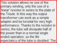
Youse guys didn't read the description of the amp... It says right here that the lightbulb is a "linear" resistor and this circuit is actually twice as efficient as one using a conventional OPT and the tubes last twice as long, because it doesn't use the primary winding!
It uses a toroid for very high performance.
🙄
Attachments
Last edited:
Err, You've completely lost me....
Yup, I read the description--and it sounds like a load of old crap to me!
Yup, I read the description--and it sounds like a load of old crap to me!
I believe Michael wanted to point out the silly claims in product derscription which have nothing to do with reality, hence the rolling eyes smiley face 😀
Let me see if I have understood this correctly:
- a light bulb is a "linear" resistor - I assume this is something different from a normal linear resistor, which a light bulb certainly isn't unless it is not glowing.
- a transformer is used, but it doesn't have a primary winding.
- halving dissipation in a Triode always doubles its life.
- the best way to halve dissipation in a Triode is not to use a lower HT and accept a lower power output, but to stick a resistor in series and accept an even lower power output.
Have I got all that? It feels like I have stumbled into a parallel universe, where the rules of physics are somewhat different. Maybe this amp was designed using alien technology, which is why we are having trouble understanding it.
- Status
- Not open for further replies.
- Home
- Amplifiers
- Tubes / Valves
- The Impressive Vetruvio GM70 SET amp.