Easier said than done. Currently there is no direct, deterministic way to inject such design constraint in the conventional windowed design protocol you are referring above. You will rely on test and trial. You will end up reinventing the wheel, just like you said.It's just another design constraint.
YES ! You'll be shaking the two membranes for nothing. Even if the two membranes tend to acoustically neutralize, from a mechanical point of view they will generate different inertia forces (different membrane mass), and those forces will be applied on non-coincident baffle points (not a coax speaker). For sure there will be a parasitic vibration conveyed by the speaker cabinet.Something I missed totally earlier was the possibility of the high pass being an exact complement of the low pass in the crossover region, so that the ringing of the woofer is 'neutralised' by the opposite ringing of the tweeter (give or take the discrepancies due to off-axis listening). If this is the case (or can be made the case), is the issue of overshoot one of a waste of power and/or needless displacement of the driver?
Your crossover won't be transparent. Your baffle enclosure will continuously play an extra-sound, correlated to your crossover design. Not what we want in high quality HiFi.
Above, I wrote "tend to acoustically neutralize" because even at the acoustic level, the neutralization process gets somewhat random, like being influenced by the speaker position in the room and other factors that may remain hidden. Try visualizing the fundamental construction difference between a 5 inch woofer membrane, and a dome or ribbon tweeter. When you have sound bouncing back to them, and reflected from them again, kind of standing waves (and this includes the reflected sound from inside the cabinet), it happens in a completely different, potentially random way, depending on your body position and your couch, facing the baffle cabinet.
Now you understand that if you are coming with a FIR exhibiting a long significant preshoot, most specialists will say "no, thank you" even if the woofer preshoot cancels the tweeter preshoot. Lots of specialists consider that any preshoot level above -20dB will destroy the listening pleasure.
Unfortunately, by experience (or By Parceval's theorem), we observe that in the real world, the sharpest the transition band and the slope (of your lowpass filter), the longer the impulse response.
Unfortunately, by experience we know that a linear-phase system has the impulse response extending before the main peak. This means preshoot.
Unfortunately, we know that both time-domain complementary (sum = unity) and frequency-domain complementary (lowpass slope same as highpass slope), only can happen with linear-phase filters.
Consider the following situation. You want to implement a steep lowpass acting like a Butterworth 48dB/octave (this is a 8th-order). You know by advance (Perceval's theorem) that you are going to have a quite long impulse response, with considerable preshoot and ringing. If you design the lowpass as linear-phase, you are obliged to have half the impulse response translating in preshoot, and the other half translating in ringing.
You may then decide to depart from a phase-linear lowpass, and tailor the phase response in such a way that only 10% of the impulse response is preshoot, and 90% ringing. Knowing that using FIRs, you have full independent control over the phase, you can get such particular lowpass exhibiting the frequency behaviour of a Butterworth 48dB/octave, however different through the phase behaviour.
Job done would you say?
Not at all because you still need to deal with the complementary highpass.
You have no degree of freedom, as for being complementary in time-domain, you need to generate the highpass by Dirac less lowpass.
What do you observe?
You observe that the resulting highpass has not the same slope as the lowpass. It has an inferior slope. Your highpass is complementary in time-domain, but not complementary in frequency-domain.
The tweeter doesn't get properly isolated from the bass frequencies.
That's the usual problem when dealing with analog complementary filters. You can view them as infinite lenght FIRs having no preshoot, only ringing. Using LTspice, design a 48db/octave Butterworth. Generate the complementary highpass by subtracting the lowpass signal from the input signal.
Guess the highpass slope.
It is only 6dB/octave!
No need to say, I'm positively impressed by the Philips DSS-930 crossover design, flirting with the preshoot audibility limit (look the woofer target time domain response), providing symmetric (lowpass and highpass) 36dB/octave slopes, and monotonic amplitude curves. All this with relatively short FIRs.
They decided for 36dB/octave lowpass and highpass slopes.
A nice generalization would be to make a redesign featuring 24dB/octave lowpass and highpass slopes. There will be less preshoot.
Another nice generalization would be to make a redesign featuring a 48db/octave lowpass slope, and a 24db/octave highpass slope.
Using such design protocol, is it feasible to end up with a 24db/octave lowpass slope, and a 48db/octave highpass slope?
Last edited:
Then you really need a better enclosure.Your baffle enclosure will continuously play an extra-sound, correlated to your crossover design.
Parceval's Relation only says that the energy under the frequency response curve equals the energy under the impulse respose curve. It states nothing about steepness of the transition band or duration of the impulse response.Unfortunately, by experience (or By Parceval's theorem), we observe that in the real world, the sharpest the transition band and the slope (of your lowpass filter), the longer the impulse response.
Not true. Consider 1st-order complementary pairs; LPF = w0/(s+w0) and HPF = s/(s+w0). Complementary, same slope, definitely not linear phase.Unfortunately, we know that both time-domain complementary (sum = unity) and frequency-domain complementary (lowpass slope same as highpass slope), only can happen with linear-phase filters.
Not necessarily true. Consider creating a LPF by drawing a straight line between a value of 1.0 (0 dB) at 0 Hz and 0.5 (-6 dB) at your chosen cutoff frequency. Extend the line such that it crosses 0.0 (-infinity dB) at twice the cutoff frequency. Now construct its complement. That will be a line extending from 0.0 (-infinity) at 0 Hz through 0.5 (-6 dB) at the cutoff frequency, to 1.0 (0 dB) at twice the cutoff frequency. Above that, it will be a flat line at 1.0 (0 dB) up to infinite frequency.You have no degree of freedom, as for being complementary in time-domain, you need to generate the highpass by Dirac less lowpass.
What do you observe?
You observe that the resulting highpass has not the same slope as the lowpass. It has an inferior slope. Your highpass is complementary in time-domain, but not complementary in frequency-domain.
This is a non-realizable filter (its impulse response will be infinite in duration), but it shows that arbitrary complementary slopes are theoretically possible. And so we can approximate them to any desired precision.
It gets very interesting, thanks. Say we define such large, symmetrical transition band having a width equal to Fc. What matters, is the woofer to exhibit a steep slope above F (with extinction at 2F), and the tweeter to exhibit the exact same steep slope below F (with extinction at DC). What computational power is needed for such particular filter featuring Fs=48kHz and Fc=3 KHz?Consider 1st-order complementary pairs; LPF = w0/(s+w0) and HPF = s/(s+w0). Complementary, same slope, definitely not linear phase. Consider creating a LPF by drawing a straight line between a value of 1.0 (0 dB) at 0 Hz and 0.5 (-6 dB) at your chosen cutoff frequency. Extend the line such that it crosses 0.0 (-infinity dB) at twice the cutoff frequency. Now construct its complement. That will be a line extending from 0.0 (-infinity) at 0 Hz through 0.5 (-6 dB) at the cutoff frequency, to 1.0 (0 dB) at twice the cutoff frequency. Above that, it will be a flat line at 1.0 (0 dB) up to infinite frequency. This is a non-realizable filter (its impulse response will be infinite in duration), but it shows that arbitrary complementary slopes are theoretically possible. And so we can approximate them to any desired precision.
The woofer -6 dB amplitude corridor will be DC to 3 kHz. The tweeter -6 dB amplitude corridor will be 3 kHz to infinite, reaching a close to 0dB response as soon as 6 kHz.
You said the impulse response will exhibit an infinite duration, in theory. Applying windowing, you may come with a practically realizable FIR. Hopefully not a 32768 tap FIR?
But wait a minute, starting from an infinite duration impulse response, eventually shortened using windowing, don't you have the impression that there will be a long, hence fatal preshoot?
Can you significantly reduce the preshoot duration, by shaping the woofer phase response, without ruining the transition band symmetry and the slope symmetry ?
Instead or relying on a FIR, can yo rely on a digital IIR?
Can it be realized in analog?
I'm not critical about such design. I'm only asking questions.
Last edited:
You dropped the context. I wrote this in the context of filters exhibiting no relative phase shifts and a perfect reconstruction. I thus never considered the 1st-order complementary pair to be a candidate.Consider 1st-order complementary pairs; LPF = w0/(s+w0) and HPF = s/(s+w0). Complementary, same slope, definitely not linear phase.
Efficient engineering is about preventing, not about curing. All things remaining equal, you'll get a better, less costly product if you don't allow the transducers to move "for nothing". In first instance, you want to avoid preshoot, as it degrades the listening pleasure. After this, you shall remain very cautious about ringing because even if it tends to be masked by the main response, it adds wasted energy transmitted to the speaker cabinet. After programming long FIRs, after executing them at great effort using powerful DSPs or x86 computers, do you really want to end up with your speaker cabinet continuously playing the crossover smears? Trying to cure the defects, you'll end up with a speaker cabinet made in unobtainium, or weighting hundreds of kilos. By the way, as explained above, your speaker will remain quite random, when exposed to standing waves (room coupling) and reflexions (your body and your couch, just in front). If planes were designed this way, none would flight.Then you really need a better enclosure.
What would your advice be for me and my setup? Basically I can run any filters I like, so where should I start?
I'm thinking along the lines of simply calculating the desired frequency amplitude response of the high pass and low pass using 'a formula', and then windowing the resulting impulse response. Presumably real only, as phase will be zero. Steph, should I make the crossover frequency a simple factor of the sample rate, as I think you suggested earlier?
Can you suggest some good formulae to start with? Something along these lines I have lifted from a paper somewhere?:
|LP| = 1/√((1-fn)2 + fn/Q2) (1)
where f is frequency normalized by the crossover frequency, f = ω/ωc. This expression yields an amplitude response with an nth order roll off and a response with magnitude
20 Log(Q) at f = 1.0. For n equal to 2 the amplitude given be Eq(1) is consistent with that of any standard 2nd order filter, Butterworth, Bessel or Linkwitz/Riley, for example. For n greater than 2 the response is only consistent with symmetric higher order filters. These include Butterworth filters (n even or odd, Q = 0.707) and Linkwitz/Riley filter (n even, Q = 0.5), but not higher order Bessel filters. The corresponding HP filter amplitude is
____________
|HP| = fn /√((1-fn)2 + fn/Q2)
I would argue that efficient engineering is about effective compromise, but that is really not the matter at hand.Efficient engineering is about preventing, not about curing.
No; according to Parseval's Relation, for a given frequency response magnitude, the corresponding energy in the time domain is exactly the same, no matter how it's "moved around" by the phase response. This means that the energy in the impulse response of the linear-phase version of a filter is exactly the same as the energy in the impulse response of the minimum-phase version of the same filter.After this, you shall remain very cautious about ringing because even if it tends to be masked by the main response, it adds wasted energy transmitted to the speaker cabinet.
Yes. That's why I'm an advocate of using Gaussian kernels (or higher-order, "Gaussian-like" kernels). I'm just pointing out that there are other options, if you are willing to tolerate overshoot and/or ringing.But wait a minute, starting from an infinite duration impulse response, eventually shortened using windowing, don't you have the impression that there will be a long, hence fatal preshoot?
I'm not sure. You're straying from theoretical concepts to issues of design. As you are the designer, it is up to you to make the necessary compromises.Can you significantly reduce the preshoot duration, by shaping the woofer phase response, without ruining the transition band symmetry and the slope symmetry ?
Again, though there is a theoretical aspect to your questions, they are more in the realm of design. As the designer, it is up to you to determine the optimum implementation.Instead or relying on a FIR, can yo rely on a digital IIR?
Can it be realized in analog?
I'm not critical about such design. I'm only asking questions.
I would argue that efficient engineering is about effective compromise, but that is really not the matter at hand.
Its an interesting aside - I'd argue that compromise is inimicable to engineering design. Real engineering is about optimisation, not compromise. The difference being that optimisation in the design space occurs in the quantum realm where synergies occur; compromise is in the classical (zero-sum) world.
A tire optimized for pavement has no tread, is completely useless in the rain, snow, mud, gravel, and dirt, and lasts less than 100 miles. How many such tires does Michelin sell?Real engineering is about optimisation, not compromise.
You may create a "Philips DSS-930 replica" thread on diyAudio.What would your advice be for me and my setup? Basically I can run any filters I like, so where should I start?
Start dealing with the crossover transfer functions, as described in the Philips DSS-930 AES paper. Look the targeted impulse responses. Look the targeted frequency responses. Fs 48 kHz, crossover at 4kHz (-6dB) and symmetric 36db/octave slopes (6th-order). For the woofer, use a 31-tap time-symmetric lowpass FIR. Which means the woofer gets linear-phase filtered. Set the woofer preshoot at -20dB (from the main peak level). Derive the complementary highpass (= Dirac less woofer). Which means there is no phase shift between the transducers. Which also means that the sum is unity in amplitude and in phase for a perfect reconstruction. Tweak the woofer impulse response in such a way that you get the desired symmetric -36db/octave slopes.
If you know no analytic way for computing the required woofer Dirac response, you'll end up writing a Visual Basic application enabling to manually edit the woofer Dirac time-domain response, and see the resulting lowpass and complementary amplitude plots in frequency-domain. Manually editing a 31-tap Dirac time-domain response is not a daunting task. You may add assistants like generating the time-domain response from various prototypes like sinus cardinal, Flat-Top, and Gauss. With scale factors "s", at the power of "p", multiplying them together, adding them together, etc. Call it reinventing the wheel, if you want. You may create assistants like stepping a parameter, and graphing the corresponding family of curves.
You then get a nice FIR-based digital crossover, however not embedding the drivers corrections.
Embedding the drivers corrections.
Use Spectra Lab 4.32 as two channel analyzer (you get the gain and the phase) by stimulating the drivers with a pink noise. There is a pink noise generator in Spectra Lab 4.32. Measure the unfiltered woofer and the tweeter, in the enclosure.
Presumably Philips relied on a 2nd-order IIR (in the shape of a controlled notch) for damping most of the 4.5 kHz woofer resonance. Depending on the woofer you are using, you also may need such kind of IIR. I wrote IIR_Lab for this, and other purposes. There is a thread on diyAudio about IIR_Lab.
Presumably Philips also added an IIR in the tweeter. Add such IIR.
Presumably Philips needed a FIR length extension for dealing with the woofer residual ringing (after the controlled notch IIR) until near extinction (-40 dB perhaps), explaining why the final woofer FIR is longer than the final tweeter FIR.
After adding the IIRs on the woofer and on the tweeter, measure them again using Spactra Lab 4.32. Gain and phase.
Enter the Bode Plots (gain and phase) in Matcad or Matlab for computing the corresponding driver Dirac responses.
Need to be cautious for computing the inverse transfer function (correction function). In the frequency domain, avoid doing corrections where anyway the target curve is -40dB. Those are the "don't care" areas Philips is talking about in the AES publication. They allow FIR simplifications.
You may write a Visual Basic application enabling to manualy tailor the driver inversion FIR, starting from the raw complementary Dirac. Then graphically visualize the resulting corrected amplitude and phase.
Make sure the woofer and the tweeter get time-aligned (same distance to your ears). Correct any mismatch with a delay line.
Following this path, you should obtain a highly flexible, efficient and precise crossover. Look the resulting DSS-930 Bode plot (gain and phase). Look the off-axis amplitude evolution at 30°, 45°, 60°.
When you are done with this, make a new crossover project using a woofer impulse response most relying on a Gaussian-centric curve, hence virtually no preshoot (say -40dB this time) and virtually no ringing (again, say -40 dB this time). Make sure you remember Berchin publication in 1999 stating that basing on a purely Gaussian time-domain woofer response (no preshoot, no ringing), the complementary highpass is only 2nd-order. This provides insufficient isolation against bass content in case you are dealing with a tweeter already featuring a 2nd-order highpass when unfiltered (sorry Berchin!). Like Berchin wrote above, for getting a more selective complementary highpass, possibly symmetric (same slope as the woofer), you need something more elaborate than a purely Gaussian curve at the power of one. If you know no analytic way to achieve this, you'll need to refine the FIR design assistant, for providing new options in such Gaussian-centric way. This way, it would be very nice to design a 48 kHz 31 tap FIR Gaussian-centric 4kHz croosover (-6 dB) featuring -40 dB preshoot and -40 dB ringing, generating symetric (lowpass and highpass) 24db/octave slopes. I really hope this to be feasible.
In a nutshell, once digital will pervade diyAudio, there will be obvious choices:
- for sure, the symmetric 6th-order with -20dB preshoot and ringing (DSS-930) (keeping in mind this only may be attainable when crossing at Fs/12)
- maybe, the symmetric 4th-order with -40dB preshoot and ringing (Gaussian-centric) (keeping in mind this may only be attainable when crossing at Fs/18 - just an idea)
- for sure, the symmetric 2nd-order with no preshoot and ringing (pure Gaussian) (keeping in mind this may be attainable for any crossover frequency)
and some assymetric design perhaps, as curiosities.
No doubt they will replace the Linkwitz-Riley arrangements. Everywhere, when digital is at work.
Last edited:
You have no degree of freedom, as for being complementary in time-domain, you need to generate the highpass by Dirac less lowpass.
What do you observe?
You observe that the resulting highpass has not the same slope as the lowpass. It has an inferior slope. Your highpass is complementary in time-domain, but not complementary in frequency-domain.
The tweeter doesn't get properly isolated from the bass frequencies.
That's the usual problem when dealing with analog complementary filters. You can view them as infinite lenght FIRs having no preshoot, only ringing. Using LTspice, design a 48db/octave Butterworth. Generate the complementary highpass by subtracting the lowpass signal from the input signal.
Guess the highpass slope.
It is only 6dB/octave!
You can of course generate derived slopes with a higher order than just 1st order. You can even achieve this in the analog domain if necessary.
In the digital domain you can use subtractive-delay topologies that offer at least 2nd order for the highpass section. See the literature by Kreskovsky or the older papers by Lipshitz and Vanderkooy. You need to use IIR though for these.
I recently did another one with IIR that does crossover and phase equalisation seperately.
Here you can have a glimpse at the step-response of the speaker, which is not the final version yet, but which still not bad IMO:
class-D amplifier PWM Verstrker SODFAs und D-Amps - DAMPF: Koaxial mit phasenlinearer Weiche
The crossover order is 3rd for the highpass and 2nd for the lowpass BTW.
Regards
Charles
sorry didn't read back enough. Lipsdhitz et al were already mentioned quite erly in this thread.
Regards
Charles
Regards
Charles
"Seeing is believing". Is there a Bode plot (amplitude and phase) of the woofer + tweeter sum?sorry didn't read back enough. Lipshitz et al were already mentioned quite erly in this thread.
You can see the amplitude response at the very same location. I havent switched-on the display of the phase response because I would have to find out where the distance can be set first. And then I would have to determine the acoustic center as well to begin with. As soon as I have time to make outside measurements and a little more finetuning I will post results.
Regards
Charles
Regards
Charles
Don't be sorry because you are implicitly coming with a new, very interesting argument.Sorry didn't read back enough. Lipshitz et al were already mentioned quite erly in this thread.
Quite amazing is that at this stage, nobody pointed out that it is mathematically impossible to have two relatively short FIRs (79 taps for the woofer and 30 taps for the tweeter) featuring symmetric 36db/octave slopes (lowpass and highpass exhibit same slopes). All this without relative phase shifts (no lobing shift). All this with a perfect reconstruction (linear in amplitude, and linear in phase).
Nobody suggested that Philips may have deliberately taken advantage of the natural drivers slopes. The DSS-930 unfiltered woofer is exhibiting a natural crossover frequency very close to 4 kHz, albeit with some resonance, followed by a nice and smooth high slope after 4 kHz. This is not by chance. This is by design, and explicitly stated in Philips DSS-930 communication at the AES in 1993, thanking the Philips Dendermonde plant for having developed the woofer that's specific in the DSS-930.
Same remark for the ribbon tweeter, to a less extend. The unfiltered tweeter natural highpass may have got deliberately used by Philips, for helping reaching a 6th-order from a natural 2nd-order.
From this perspective, could it be the DSS-930 is basing on a Linkwitz-Riley 6th-order, globally phase-compensated thanks to digital?
Would be interesting to model a Linkwitz-Riley 6th-order on LTspice, then determine what kind of global phase-compensation is needed.
I however have the impression that the DSS-930 features sharper transition bands than a Linkwitz-Riley 6th-order.
Last edited:
I certainly like the idea of attaining the best possible performance.
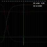
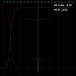
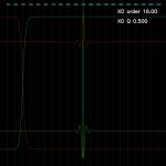
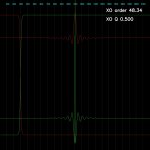
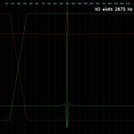
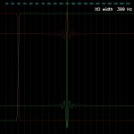
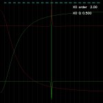
But just trying to get an intuitive grasp of all this, I've written a program simply to display the frequency and impulse responses of your standard kind of low pass filter (Gaussian derived?), plus the complementary high pass filter. I can animate sweeps through cutoff frequency and order. Just as a comparison I can do the same for my original naive 'linear crossover' filter.
The thing is, assuming the program's more-or-less correct, I'm finding it hard to make a bad one.
No great surprises at all: the linear crossover filter just isn't as terrifyingly bad as I thought it would be - pretty much similar to the 'correct' filter of a similar crossover steepness. And I'm not seeing 'nulls' or anything interesting in the ringing when the cutoff frequency is some factor of the sample frequency.
So, without any maths, is it the case that if I fitted some 'grab handles' to the frequency response I could subtly move things around and happen upon permutations that suppressed the amplitude of the ringing? (Or, as steph suggested earlier use genetic algorithms etc. - I like that idea). Or if I did that would I correspondingly increase the duration of the ringing instead, or degrade the effectiveness of the crossover? Can I expect a startlingly better performance by optimising the standard filter further or is it very much at the margins?
(Sample freq is 44100 Hz, FFT size is 512 in these images. Display axes are lin-lin. The impulse response has been windowed with a raised cosine window).
Attachments
-
 STD cutoff 3000Hz order 4.00.JPG116.3 KB · Views: 219
 -
 STD cutoff 3000Hz order 8.00.JPG114.6 KB · Views: 231
 -
 STD cutoff 3000Hz order 16.00.JPG113.9 KB · Views: 213
 -
 STD cutoff 3000Hz order 48.34.JPG114 KB · Views: 221
 -
 LIN cutoff 3000Hz width 1348Hz.JPG110.7 KB · Views: 213
 -
 LIN cutoff 3000Hz width 2875Hz.JPG112 KB · Views: 125
 -
 LIN cutoff 3000Hz width 399Hz.JPG110 KB · Views: 128
 -
 STD cutoff 3000Hz order 2.00.JPG117.1 KB · Views: 115
Last edited:
So, without any maths, is it the case that if I fitted some 'grab handles' to the frequency response I could subtly move things around and happen upon permutations that suppressed the amplitude of the ringing?
Not suggesting I'm going to do that, by the way, but would it be a valid way to do it? Is the maths of finding the optimal filter 'pure', or does it involve some trial-and-error?
- Status
- Not open for further replies.
- Home
- Source & Line
- PC Based
- The importance of crossover steepness