well, I should say that everything up to 10% of Iq change with 10% of rail change is acceptable
5% @ 10% is decent
1% @ 10% is great
so, what's 55mA/2V5?

5% @ 10% is decent
1% @ 10% is great
so, what's 55mA/2V5?
Very impressive project. Congratulations.
Could you explain the function of Zener D1, D2 and P1 , P2?
Could you explain the function of Zener D1, D2 and P1 , P2?
The zener diodes are being operated as "ordinary" diodes. An "ordinary" diode with an appropriate voltage drop could be substituted. I could get deeply into the circuit equations, but basically the diodes allow the variations of the bias current (voltage across the drain sense resistor) to modulate the current through the LED more effectively.
Also, for large output signals, when the output FET is turned on and drawing a very large current, the diode stops conducting, thus limiting the current into the LED to prevent the optocoupler output transistor from discharging the integrating capacitor (low pass filter) between the FET gates.
P1 adjusts the output offset voltage.
P2 adjusts the FET bias current.

What value are these zeners? 4.7V?
Another question what's the max voltage one can use for the power supply? I presume this is dependent on the output devices one uses?
Another question what's the max voltage one can use for the power supply? I presume this is dependent on the output devices one uses?
I have been using 6.9V zeners, but I am not sure if it matters much. I haven't tried an ordinary diode like a 1N4148 but it would probably work. There are lots of parameters that interact: quiescent voltage across the sense resistors, the optocoupler current transfer ratio, ,,,
Max power supply voltage: right now it is limited to +/-30V be the opa551 opamp, but the opa445 has +/-50V max rails.
The other limits are the limits of the single output FETs and the heatsinks.
My intent with the current implementation was a FirstWatt scale amplifier, both in rail voltages and heatsink requirements.
where nominally Ibias=1.3A and Vrail=24Vwell, I should say that everything up to 10% of Iq change with 10% of rail change is acceptable
5% @ 10% is decent
1% @ 10% is great
so, what's 55mA/2V5?
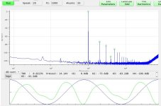
d(Ibias)/d(Vrail) = -22mA/V => -4% @ 10%
Again, these are simulated results, I haven't yet measured.
The interesting thing about the undegenerated push-pull source-follower is that with the proper choice output FETs the behavior smoothly transitions to class AB at high output po lwer levels, assuming that to power rails are high enough. Yesterday is bench tested my prototype amp:.How to include the Class AB feature of the M2OPS (with the LM385s) with this ?
https://www.diyaudio.com/community/...in-class-a-b-and-maybe-a-power-whammy.390636/
Thinking out loud,
Patrick
- Rail voltages: +/-24V.
- Bias current: 1.3A
- Output load: 4 Ohms
I couldn't test at much higher output levels being limited by +/-24V rails and current limits of the SMPS.
Attachments
Hi lhquam,
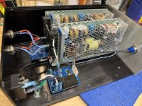
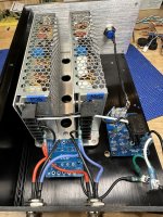
The very good results you shared using the Meanwell switchers wired for a bipolar psu gave me motivation to improve the setup I was using. I reclaimed an old chipamp chassis to build an external power supply using a pair of Meanwell HRP-200-24 units already in my stash. I used a GLB pcb to create the common connection with 47R in series to star gnd.
Hopefully will get to put it into service soon!
Attachments
Can you explain further what the 47R resistor does? Did you possible mean 0R47 for use as a ground breaker?I used a GLB pcb to create the common connection with 47R in series to star gnd.
The GLB board made a convenient place for the smps V+, V- series connection and replaced the thermistor in your psu diagram from an earlier post. Instead of the typical 10R thermistor there is a 47R//100nF and bridge rectifier.
I am at a stage in the Holy Grail (aka. ZD25-Mini) listening and bench test evaluation that I highly recommend that others build this amplifier.
I have an new and improved PCB layout and if there is enough interest I will have some fabricated and will make the Gerber files available.
I have tested five different sets of output FETs and the FQA28N15/FQA36P15 FETs are the clear winner. That doesn't mean that other FET pairings will not give good results. I will soon post the comparisons.
The PS can be either SMPS or linear. I have tested both. The linear supply is more expensive, but has better known properties w.r.t. noise and some other potential issues.
Of course, I am all about building experimental amplifiers. I have several board sets, chassis and power transformers that I treat like LEGOs.
I already have some IXTQ36N30P, IXTQ36P15P and IXTQ26P20P on hand. Those were to be used for F5m experimentation and might be interesting in the ZD25-mini as well. It would be interesting to see your test results so far.
Edited:
The FQA28N15 parts are no longer manufactured and the FQA36P15 are difficult. Did you mean IXT_ instead?
Last edited:
I think there will be more than a few interested in building your ZD25 Mini 
I'm interested! What is the input impedance of your output stage? 10K? I'm thinking about only using the output stage after my preamp that consist of the Iron Pre or the Front End 2022.
Hubert
Hubert
The benefit compared to those with source degeneration depends a lot on the MOSFET pair.
For example, our simulations show that there is no advantage in using this for the 2SK3497/2SJ618 pair.
Rather it makes things much worse.
So you need to check the specific MOSFET combination.
Also you should distinguish between the distortion of the OPS only, and that in a closed loop circuit with e.g. the OPA551.
Patrick
I did mean the Fairchiild FQA28N15 and FQA36P15.Of course, I am all about building experimental amplifiers. I have several board sets, chassis and power transformers that I treat like LEGOs.
I already have some IXTQ36N30P, IXTQ36P15P and IXTQ26P20P on hand. Those were to be used for F5m experimentation and might be interesting in the ZD25-mini as well. It would be interesting to see your test results so far.
Edited:
The FQA28N15 parts are no longer manufactured and the FQA36P15 are difficult. Did you mean IXT_ instead?
I have tested the pairing of IXYS IXTQ36N30P and IXTQ36P15P FETs and they would be acceptable.
I have not tested FQA28N15 (still available) with IXTQ36P15P. Worth a try.
I just ordered some FQA28N15 parts. They look like a good match for the FQH44N10 that I already have.
- Home
- Amplifiers
- Pass Labs
- The Holy Grail Follower Output Stage