Will be very interested in any thoughts or observations you might have with the different PSU's - SMPS vs linear.
I cranked the LRS-200N2-24 voltages up to 29V and made measurements. The output FETs I selected were very rare, exact gm matches on an 8R load line. The front end was configured for no global feedback. With 29V rails and 1.25A bias current the temperature rise of the heatsinks was 27C.
Here are sweeps of THD and harmonics for the two channels (columns) into 8R and 4R loads (rows). With an 8 Ohm load the amplifier is voltage limited to 44 Watts. With a 4 Ohm load the amplifier is voltage limited to 75 Watts.

Here are sweeps of THD and harmonics for the two channels (columns) into 8R and 4R loads (rows). With an 8 Ohm load the amplifier is voltage limited to 44 Watts. With a 4 Ohm load the amplifier is voltage limited to 75 Watts.
Last edited:

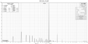
Here is a noise spectrum. -24dB corresponds to 4V peak (2,82Vrms). The noise above 40kHz is due to the noise shifting of the ADC in my measurement system.

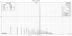
Here is a harmonic spectrum for 16 Watts, 1kHz into an 8R load.

Here is a harmonic spectrum for 16 Watts, 1kHz into an 8R load.

The both work well. The long term reliability and failure modes of the linear supply are better known.Will be very interested in any thoughts or observations you might have with the different PSU's - SMPS vs linear.
The advantages of the switching mode power supplies (SMPS) are:
- regulated and adjustable output voltage
- less expensive
- more compact and lower weight
Last edited:
Power MOSFETs without source resistors makes a difference.SMPS? Never heard of it.... 🙂
Those are impressive figures. This is one mean output stage, eating that 4R load for lunch...
Lets say, which PSU does not get in the way of the music the least.Maybe you can define ”better”…
I cannot figure out why these FQA28N15 and FQA36P15 work so well in this output stage, particularly with 4 Ohm loads. I keep rechecking my instrumentation and measurements but cannot find problems. The measured distortions are far lower than shown by simulations.SMPS? Never heard of it.... 🙂
Those are impressive figures. This is one mean output stage, eating that 4R load for lunch...
Since I now have an extra complete amplifier, I can revert the role of the prototype chassis to do some new experiments using different FETs. I will start with IRFP240 and IRFP9240 FETs, since they have been so thoroughly measurement and modeled and see how simulations compare to bench tests of the ZD25-Mini.
My speakers are 4R rated and medium sensitivity, hence my interest in these square law amps the past few years. My plan was to maybe run it without GFB since the performance holds up so well. Just local feedback with your onboard opamp solution or one of my many discrete front ends that I can bolt to the back wall of my amps. And there I could just share the amp rails, or use an outboard boosted and regulated supply, built and ready... lots of options..
*edit - Thanks so much for your work on this and making the project a reality with offering the matched FET's, PCB's, and support to make it all happen.
*edit - Thanks so much for your work on this and making the project a reality with offering the matched FET's, PCB's, and support to make it all happen.
Last edited:
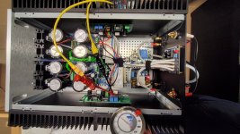
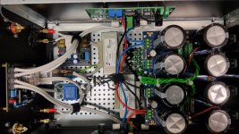
Here is the current state of my HGF version squeezed in a monoblock chassis.
The cooking process was easy and idle Iq is set to 1.4A with a offset of a few mV. The heatsink temperature rises from 20 °C to 43 °C which corresponds to about 70W disspation for each stereo channel. This is still pleasant to touch.
Next I did a few quick measurements before connecting test speakers. It turned out that the distribution of harmonics of the 1 kHz measurement frequency in FFT was good-natured and fell nicely with increasing frequency, but I don't really like the noise spectrum. This still needs to be improved. Especially 100 Hz and its harmonics are still too high.
I can hear it on the speaker (90 dB efficiency) if I put my ear directly to the midrange speaker.
I am afraid that the small spaces between PSU components and amp PCBs in the narrow monoblock could be the cause.
Any advice is appreciated.
Anyway, there is one thing that I really like, namely the damping factor. The measured output impedance as delta between 4 and 8 ohm load is 0.029 ohm. This theoretically means DF > 275
Attachments

Maybe Mr. power supply could be evicted and moved into a new distant home as punishment. Now only allowed to talk in a civilized manner through an umbilical. Each channel board in the amp chassis could have their own final "C's", which should allow for slightly better separation... likely be a good thing (use favorite audiophool words, better imaging, improved soundstage, blah, blah)..
In the 1st image I cannot tell where the ground wires from the HGF PCBs go. The velcro tie hides them. I see one black wire connecting to rectifier/capacitor board, and the two black wires from the HGF PCBs, but I cannot see where they are connected?Here is the current state of my HGF version squeezed in a monoblock chassis.
The cooking process was easy and idle Iq is set to 1.4A with a offset of a few mV. The heatsink temperature rises from 20 °C to 43 °C which corresponds to about 70W disspation for each stereo channel. This is still pleasant to touch.
Next I did a few quick measurements before connecting test speakers. It turned out that the distribution of harmonics of the 1 kHz measurement frequency in FFT was good-natured and fell nicely with increasing frequency, but I don't really like the noise spectrum. This still needs to be improved. Especially 100 Hz and its harmonics are still too high.
I can hear it on the speaker (90 dB efficiency) if I put my ear directly to the midrange speaker.
I am afraid that the small spaces between PSU components and amp PCBs in the narrow monoblock could be the cause.
Any advice is appreciated.
Anyway, there is one thing that I really like, namely the damping factor. The measured output impedance as delta between 4 and 8 ohm load is 0.029 ohm. This theoretically means DF > 275
@william2001
I agree this is complaining at a high level. Relegating PSU to a separate housing would be the final solution if all civilized measures fail.
But it is now too late to speculate about moving it to a new distant home anyway, as the highly valued umbilical was cut off immediately after the last soldering process
@lhquam
The two black wires from the HGF PCBs and the wire from PSU board are connected to the star ground seen underneath the velcro tie.
Good. Does RCAgnd connect to GndR of one of the HGF PCBs?The two black wires from the HGF PCBs and the wire from PSU board are connected to the star ground seen underneath the velcro tie.
I didn't use the GND breaker. RCAgndL ist connected to InGndL and RCAgndR to InGndR with screened black wires under the upper chassis mount rail.
Attachments
Last edited:
I don't have any suggestions regarding the 50Hz harmonics, other than an umbilical, simpler more compact supply, or SMPS.
Try making the spectral measurements with the ADC inputs connected to the GND and Out test points on the PCB. Sometimes there are unsuspected ground loops involving the test equipment.
Try making the spectral measurements with the ADC inputs connected to the GND and Out test points on the PCB. Sometimes there are unsuspected ground loops involving the test equipment.
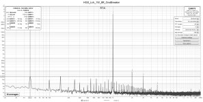
FFT spectrum directly on the PCB test point TPout showed a lower level of 50 Hz and its harmonics.
So, the layouts of the connections from PCB -> speaker protector -> Fast-on output connector were the culprits. The spacing to 159ZJ chokes was rearranged and GNDR breaker used. The result is visible and I can live with this 50 Hz under 35 uV.
This should be enough of the dialysis and now let listen to the music and exchange the experiences.
Many thanks to everyone who made this great project possible, as there are still so many variants to try out
Attachments

- Home
- Amplifiers
- Pass Labs
- The Holy Grail Follower Output Stage