That link isn't working for me.Did you consider using those crimp thingies? they say it's very helpful…
I use lots of crimped connections, so I'm open to anything. As a reasonable rule of thumb, I like to solder the input connections b/c I generally use fairly small diameter wire, but still I'll take a look. Would you try posting the full web link, please? Maybe it got cut a bit with the insert link tool. Thanks!
Correct.^ Thank you! I assumed as much, but still...
Confirming
- the board with the ground loop break In- goes to GNDR (with RCA GND).
- the board without the ground loop break In- goes to GND (with RCA GND).
Correct?
Edited to add - the reason I ask is because I've never used a ground loop breaker on only one amp PCB, and the instructions clearly say to do it only on one board. I assumed that the GNDR was now the new "audio GND" for the amp boards and that both amp boards would use that as the new "ground reference" vs. one using GND and one using GNDR, but I still have a lot to learn... and it made my brain short out.
Didn't get a chance to do anything yesterday. The day got away from me.
Had some time this morning to 'rough everything in'.
Sets up beautifully. Lynn, thank you again for the wonderful guide. It makes things so much easier for folks like me that might truly understand 10% and cringe every time they flip the mains switch on a new project.
Some observations -
My channel with the ground loop breaker takes a good bit longer to stabilize than the channel without. On a "fresh" power cycle (did not check cap charge) the bias on the board without the ground loop break is up and "stable" within 10s. The channel with the ground loop break takes about a minute, and it slowly climbs its way on up. If this is something to consider looking into a little deeper, I definitely will.
Seems to be very low (relatively speaking) change in bias or offset as the sinks warm up. Nice!
Pots (even if they are single turn) react nicely and smoothly to input. Easy to dial in bias and offset w/o worrying that one little nudge is going to set things aflame.
Plays music through test speakers and a phone just fine. No hum. Makes music in both channels. No turn on / turn off thump.
I noticed that for some reason this PSU assembly didn't have my normal CL-60 "ground lift" thermistor, but if it doesn't have any hum, with my more sensitive speakers, I won't worry about it. I noticed it in the schematic, but... I assume it's not strictly necessary.
A question -
My basic calcs show that with 24V rails I should be about 60W dissipation per channel with 0V137 across the sense resistors. That matches the notes to get sinks appropriate to 60-70W. My skills in this are still shaky, but essentially ~2A5 Iq per channel. I seem to have more than enough heatsink. In the guide it notes "Thus for a nominal 4 Ohm speaker, a +/-23V (or less) supply might be fine with the bias current adjusted to what your heatsinks can handle". All of my speakers are <8R nominal. Dissipation per device is 30W ish. I looked at the spec sheets and tried to make some heads or tails of it. With 9240s / 240s, I've always had in my notes to not exceed 35W dissipation per device as a general rule of thumb. The highlights of the 36P15 note (as example) that it's -36A, -150V. Similarly for the 26N15, it notes 33A, 150V.
So, it would seem that we're WELL below rated specs, and if I wanted to try... ~100W of dissipation per channel / 50W per device I should be fine, as long as temps are below "hot" correct? I may do some THD / Power measurements at both if I get a chance to see if the added dissipation is "worth it". I don't plan to use this amp to go crazy.
If it's stable around this time tomorrow morning, I'll see how she does in a system not using a phone as a source etc. and with more sensitive speakers. Could change my decision re: the ground lift CL-60.


didn’t find it anymore here’s a similar: https://www.furutech.com/2013/01/16/1668/full web link, please?
Though I don’t think you don’t already know or use them, they‘re obvious parts… (and with „they“ in the previous post, I meant ZM and 6L6…)
Last edited:
^ Ah, yes I have seen those. Not suitable to my task for input wiring. I typically use 24 or 30AWG for input wiring. Below are the parts listed.
GS-21P (I.D. :2.1mmXOverall long:10mm) for 14 AWG
GS-28P (I.D. :2.8mmXOverall long:10mm) for 12 AWG
GS-35P (I.D. :3.5mmXOverall long:10mm) for 10 AWG
GS-46P (I.D. :4.6mmXOverall long:10mm) for 8 AWG
GS-83P (I.D. :8.3mmXOverall long:20mm) for 4 AWG
GS-90P (I.D. 9.0mmXOverall long:20mm L) for 2 AWG
2AWG input wiring may be fun!!
Thanks again though for trying to help find solutions. I direct soldered them, but I'm always looking for new stuff to try out.
Iq is 1A25 from what I can see, no? .137/.11but essentially ~2A5 Iq per channel.
^ I thought with two devices per channel, you doubled it... I thought 1A25 would be for one device.
Your total consumption calc is correct, but the standing current is 1A25. Since its a bipolar supply, one device is handling the neg, the other the positive. You could also look at it as 1A25*48v (-24-0-24) for total current consumption. Or at least that’s the way I understand it.
additionally this is for one channel....so the consumption for the complete amp in idle is 2x 48V*1A25- so normally a 4U 400mm housing should be enough.
chris
chris
^ Definitely. I mentioned above that I was using the 5U only because it is the only chassis I had empty. The sinks are barely warm at the 60W per channel. Thus my question above re: bumping up the Iq to result in roughly 100W dissipation per channel, which is roughly where I've found my sinks with that chassis to get to ~45C / 50C depending on ambient temps, number of devices per channel and how well they're spaced out / placed on the sinks etc.
Truly appreciate you guys!
Truly appreciate you guys!
^ Agreed, but if that was directed toward me, I'm not using a switch mode supply. I wired mine using the wiring diagram provided for the linear supply.
IAIMH - Current flows through the devices (when "turned on" - biased) from one power rail to the other power rail. Each device is like a "faucet". If each faucet is "turned on" the exact same amount, DC output offset voltage is exactly 0 VDC. If the top faucet is open a little more, or vice versa, that's where you see a DC voltage (pressure) offset at the point between the pair. A plus or minus voltage depending on which side, top or bottom, is pushing harder.
^ Truly appreciate that. I've understood that concept (I think) for a while now from when I built my first F5 and was struggling to understand the "bias" and "offset" pots. To me, it was just biasing both devices 'equally' vs. one "controlling" offset and one controlling bias. When you reached equal / opposing bias, the offset is nulled. Heck, I still may have that all wrong.
Most importantly, I really like the visual aspect of your description. That's also why I always have my probes set per the speaker outs so, if there is an issue, I can see what "side" is more open or closed relative to the other. Early on, I never understood why the polarity of the offset mattered so much when people were posting issues for troubleshooting.
I just have this odd way of compartmentalizing concepts and not seeing the full picture. When I looked at Cody's comment, I did more of a 🤦♂️ than a , but there was a little
  at my oversight. I still go back to when someone showed me how current flow works in Class-A push-pull between the N and P channel devices. Once I associated it with my feet in clips on a bike and pulling with one leg while pushing with the other... for some reason that 'stuck'. I need to always say in my mind that the voltage used is (in whatever equation) always the potential DIFFERENCE between the two points in question vs. the voltage in reference to a 0V or GND. In this situation, it's obvious (to most) that the devices for all intents and purposes sit right between the rails ... thus the -24V to + 24V => 48V difference.
I may never actually understand electricity, but I've got some really good notes for how to generally not blow things up.
I just need a good smack upside the head every now and again like an old TV.
Thanks again!
Most importantly, I really like the visual aspect of your description. That's also why I always have my probes set per the speaker outs so, if there is an issue, I can see what "side" is more open or closed relative to the other. Early on, I never understood why the polarity of the offset mattered so much when people were posting issues for troubleshooting.
I just have this odd way of compartmentalizing concepts and not seeing the full picture. When I looked at Cody's comment, I did more of a 🤦♂️ than a
 , but there was a little
  at my oversight. I still go back to when someone showed me how current flow works in Class-A push-pull between the N and P channel devices. Once I associated it with my feet in clips on a bike and pulling with one leg while pushing with the other... for some reason that 'stuck'. I need to always say in my mind that the voltage used is (in whatever equation) always the potential DIFFERENCE between the two points in question vs. the voltage in reference to a 0V or GND. In this situation, it's obvious (to most) that the devices for all intents and purposes sit right between the rails ... thus the -24V to + 24V => 48V difference.
 I may never actually understand electricity, but I've got some really good notes for how to generally not blow things up.

I just need a good smack upside the head every now and again like an old TV.
Thanks again!
"The channel with the ground loop break takes about a minute, and it slowly climbs its way on up."Didn't get a chance to do anything yesterday. The day got away from me.
Had some time this morning to 'rough everything in'.
Sets up beautifully. Lynn, thank you again for the wonderful guide. It makes things so much easier for folks like me that might truly understand 10% and cringe every time they flip the mains switch on a new project.
Some observations -
My channel with the ground loop breaker takes a good bit longer to stabilize than the channel without. On a "fresh" power cycle (did not check cap charge) the bias on the board without the ground loop break is up and "stable" within 10s. The channel with the ground loop break takes about a minute, and it slowly climbs its way on up. If this is something to consider looking into a little deeper, I definitely will.
Seems to be very low (relatively speaking) change in bias or offset as the sinks warm up. Nice!
Pots (even if they are single turn) react nicely and smoothly to input. Easy to dial in bias and offset w/o worrying that one little nudge is going to set things aflame.
Plays music through test speakers and a phone just fine. No hum. Makes music in both channels. No turn on / turn off thump.
I noticed that for some reason this PSU assembly didn't have my normal CL-60 "ground lift" thermistor, but if it doesn't have any hum, with my more sensitive speakers, I won't worry about it. I noticed it in the schematic, but... I assume it's not strictly necessary.
A question -
My basic calcs show that with 24V rails I should be about 60W dissipation per channel with 0V137 across the sense resistors. That matches the notes to get sinks appropriate to 60-70W. My skills in this are still shaky, but essentially ~2A5 Iq per channel. I seem to have more than enough heatsink. In the guide it notes "Thus for a nominal 4 Ohm speaker, a +/-23V (or less) supply might be fine with the bias current adjusted to what your heatsinks can handle". All of my speakers are <8R nominal. Dissipation per device is 30W ish. I looked at the spec sheets and tried to make some heads or tails of it. With 9240s / 240s, I've always had in my notes to not exceed 35W dissipation per device as a general rule of thumb. The highlights of the 36P15 note (as example) that it's -36A, -150V. Similarly for the 26N15, it notes 33A, 150V.
So, it would seem that we're WELL below rated specs, and if I wanted to try... ~100W of dissipation per channel / 50W per device I should be fine, as long as temps are below "hot" correct? I may do some THD / Power measurements at both if I get a chance to see if the added dissipation is "worth it". I don't plan to use this amp to go crazy.
If it's stable around this time tomorrow morning, I'll see how she does in a system not using a phone as a source etc. and with more sensitive speakers. Could change my decision re: the ground lift CL-60.


That is strange, but it not related to the ground loop breaker. Carefully check all resistor values and solder joints. If all else fails, try swapping either the NFETs or PFETs between channels to see if the behavior is FET related.
"I noticed that for some reason this PSU assembly didn't have my normal CL-60 "ground lift" thermistor, but if it doesn't have any hum, with my more sensitive speakers".
You should have a thermistor from analog ground to chassis ground as shown in the "Chassis Wiring" diagrams.
1A25 with 24V rails sounds like a good starting point for the bias. Listen to the amp for a while to let it run in with all the new components. Then goose the bias to 1A4 or 1A5 and check the temp on your heatsinks. Listen to that to see if the different operating point sounds better in your system.
I have been running around 1A4 or a little higher with 26V rails in my F5m. The N-type FET is the same and the P-type is different, but this has been a good sounding combination.
I have been running around 1A4 or a little higher with 26V rails in my F5m. The N-type FET is the same and the P-type is different, but this has been a good sounding combination.
Well, with Lynn's incredible help, she's up and making beautiful music. I'd have never figured out the issue with the suspect board. Two resistor changes to a new value to allow it to bias up properly and we're off and running like a herd of turtles.
I couldn't resist hooking it up to some actual speakers to give it a listen. Even after all the abuse I gave that one poor board taking it in and out and in and out etc. the thing is rock stable (knock wood).
I biased it up to ~175mV across the sense resistors ... so ~75W dissipation per side. I was also targeting ~50W@4R. I wasn't being precise.
Here's the current state of affairs.
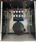
I'll be changing PSUs at some point down the road. I think it 'deserves' something with a little less ripple. That will also give me a chance to try a few other layouts. I'm not thrilled that my nice clean DC runs right under my PEM. Either way... I'm tickled pink.
I did a few VERY quick and DIRTY measurements. Even when test speakers don't fold in on themselves, I've been burnt. So, I do at least a few basic things before anything gets hooked up to a 'system'.
1W FFT @ 4R and 8R
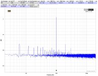
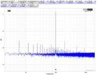
8W FFT @ 4R and 8R
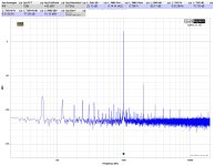
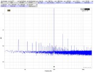
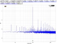
Max output FFT before clipping (roughly) 4R and 8R

Time domain clipping behavior 4R and 8R
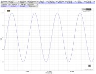
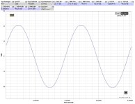
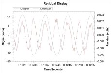
Distortion is low enough that you have to 'pump it up a bit' for this software to show a clean visual of the residual. Nice positive 2nd (best I can tell).
And a quick and dirty power vs. THD.
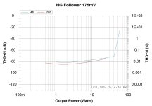
There's no questioning the performance. It's close to ruler flat when it comes to distortion throughout the power band.
But wait... how does it sound? Gimme a few hours at least. For now... I'm getting used to it. Initial impressions are quite good.
Thank you, Lynn!!!!
I should add this to my signature - Should anyone take any measurements I post as gospel, NO! I'm learning. OH! I don't normally do this, but I knew I'd redo these down the road... My laptop was connected to mains during measurements. It was about dead, and I didn't feel the need to wait to charge it or grab a battery brick.
I couldn't resist hooking it up to some actual speakers to give it a listen. Even after all the abuse I gave that one poor board taking it in and out and in and out etc. the thing is rock stable (knock wood).
I biased it up to ~175mV across the sense resistors ... so ~75W dissipation per side. I was also targeting ~50W@4R. I wasn't being precise.
Here's the current state of affairs.

I'll be changing PSUs at some point down the road. I think it 'deserves' something with a little less ripple. That will also give me a chance to try a few other layouts. I'm not thrilled that my nice clean DC runs right under my PEM. Either way... I'm tickled pink.
I did a few VERY quick and DIRTY measurements. Even when test speakers don't fold in on themselves, I've been burnt. So, I do at least a few basic things before anything gets hooked up to a 'system'.
1W FFT @ 4R and 8R


8W FFT @ 4R and 8R


Max output FFT before clipping (roughly) 4R and 8R


Time domain clipping behavior 4R and 8R


Distortion is low enough that you have to 'pump it up a bit' for this software to show a clean visual of the residual. Nice positive 2nd (best I can tell).

And a quick and dirty power vs. THD.

There's no questioning the performance. It's close to ruler flat when it comes to distortion throughout the power band.
But wait... how does it sound? Gimme a few hours at least. For now... I'm getting used to it. Initial impressions are quite good.
Thank you, Lynn!!!!
I should add this to my signature - Should anyone take any measurements I post as gospel, NO! I'm learning. OH! I don't normally do this, but I knew I'd redo these down the road... My laptop was connected to mains during measurements. It was about dead, and I didn't feel the need to wait to charge it or grab a battery brick.
- Home
- Amplifiers
- Pass Labs
- The Holy Grail Follower Output Stage