

Mine came yesterday and is feeling neglected already...
BUT look at what also FINALLY arrived. Now, why they had to ship them in a completely separate box... I dunno...
Now... when can I get back to the bench and get this built... ??????? Oh, now I gotta order R21 boards unless anyone has a few spares they can throw my way.

BUT look at what also FINALLY arrived. Now, why they had to ship them in a completely separate box... I dunno...
Now... when can I get back to the bench and get this built... ??????? Oh, now I gotta order R21 boards unless anyone has a few spares they can throw my way.
I thought you already had Tombo's R21 pcb's. I have some though if you need them.
^ I was a Dodo per usual and ordered his amp boards, but I forgot to add the R21 boards to the order. I figured I'd just wait until the next "big" PCB order to add them since it looked like it would be until the next ice age to get the parts.
I'll shoot you a note so we don't bog down Lynn's cool thread.
Thanks!!!
I'll shoot you a note so we don't bog down Lynn's cool thread.
Thanks!!!
I got a little time after supper to put together the boards (sans MOSFETs).
I chose to go the "Basic/Baseline" route for the first (and maybe only) iteration. I read the lovely guide and picked up a lot more understanding re: the gain variance. The instructions for optimizing the bias circuit through altering R11 and R12 were crystal clear, and I feel like I could have handled it. However, I'm good with the "nominal", and yes, I would be worried about bias current becoming temporarily very large if I left them completely out.
The gain is perfectly fine with 'standard' values, but I might tweak it lower down the road. No need for the XLR inputs for me on this amp. Given the low distortion already, and the fact that if I'm careful, I can keep noise down... no worries. With that said, I went ahead and installed the ground loop breaker. I'm just weird that way.
Lynn, the build guide is wonderful. It's about the 4th time I've read it, and each time I read it... I pick up a tad bit more.
It will be a wonderful experimenter's platform, but for now... I'll see how it works out. If I've done anything particularly nutso that someone spots, please shout it out.
Plan is to perhaps steal an open 5U/400 chassis... which will be overkill perhaps, but it's the only thing that doesn't have an amp in it at the moment. I'll likely start off with a "basic" First Watt type PSU ... 18VAC 400VA toroid / 24V rails (ish) / CRC. Then, it will be highly likely that I'll swap that out.
Let's see what tomorrow brings in terms of free time.
Thanks again, L,ynn, for making your designs available, and kudos for taking the time to help teach by writing your methodology and how your projects evolve.

Edited for clarity and to add that I haven't installed test points or the jumper to the FE yet either (clearly).
I chose to go the "Basic/Baseline" route for the first (and maybe only) iteration. I read the lovely guide and picked up a lot more understanding re: the gain variance. The instructions for optimizing the bias circuit through altering R11 and R12 were crystal clear, and I feel like I could have handled it. However, I'm good with the "nominal", and yes, I would be worried about bias current becoming temporarily very large if I left them completely out.
The gain is perfectly fine with 'standard' values, but I might tweak it lower down the road. No need for the XLR inputs for me on this amp. Given the low distortion already, and the fact that if I'm careful, I can keep noise down... no worries. With that said, I went ahead and installed the ground loop breaker. I'm just weird that way.
Lynn, the build guide is wonderful. It's about the 4th time I've read it, and each time I read it... I pick up a tad bit more.
It will be a wonderful experimenter's platform, but for now... I'll see how it works out. If I've done anything particularly nutso that someone spots, please shout it out.
Plan is to perhaps steal an open 5U/400 chassis... which will be overkill perhaps, but it's the only thing that doesn't have an amp in it at the moment. I'll likely start off with a "basic" First Watt type PSU ... 18VAC 400VA toroid / 24V rails (ish) / CRC. Then, it will be highly likely that I'll swap that out.
Let's see what tomorrow brings in terms of free time.
Thanks again, L,ynn, for making your designs available, and kudos for taking the time to help teach by writing your methodology and how your projects evolve.
Edited for clarity and to add that I haven't installed test points or the jumper to the FE yet either (clearly).
Last edited:
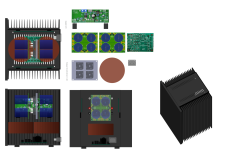
Here is a chassis design that I am currently working on, using the HeatsinkUSA 10.08 series heatsinks. It shouild be relatively inexpensive to build, but does require some metal fabrication work for the panels.


Hi folks / Lynn -
OK... I am having a brain fade...
When using the ground loop breaker on the one side. It is abundantly clear to use GNDR for wiring the input for that side.
Now... wait for it... here's the dodo question. When shorting In- to "ground" for the input when not using XLR inputs, should I short it to GND or GNDR for that channel?
AND...
For the side without the ground loop breaking components ... should I wire the input to GND or GNDR and which should I short in- to?
I know... I know... Even after all the reading I do re: ground loops my brain still spins. I just want to wire this properly and not defeat the purpose of the ground loop breaker (or make it worse).
If I were using the terminal block... I'd just not worry about it, but I generally direct solder the inputs to the boards... and once I mount them, it's a pain to move them around. If ZM's watching... yet another excuse to not direct solder.
Thanks!!!
Got my package today
Thank you guys .That will be an interesting comparison between my F4 and the grail.
Thank you guys .That will be an interesting comparison between my F4 and the grail.
In- needs to connect to the same place as the RCA GND. In my wiring I use 3-wires from the input terminal bnlock to the RCA connector and tie In- to the RCA GND.Hi folks / Lynn -
OK... I am having a brain fade...
When using the ground loop breaker on the one side. It is abundantly clear to use GNDR for wiring the input for that side.
Now... wait for it... here's the dodo question. When shorting In- to "ground" for the input when not using XLR inputs, should I short it to GND or GNDR for that channel?
AND...
For the side without the ground loop breaking components ... should I wire the input to GND or GNDR and which should I short in- to?
I know... I know... Even after all the reading I do re: ground loops my brain still spins. I just want to wire this properly and not defeat the purpose of the ground loop breaker (or make it worse).
If I were using the terminal block... I'd just not worry about it, but I generally direct solder the inputs to the boards... and once I mount them, it's a pain to move them around. If ZM's watching... yet another excuse to not direct solder.
Thanks!!!
^ Thank you! I assumed as much, but still...
Confirming
Correct?
Edited to add - the reason I ask is because I've never used a ground loop breaker on only one amp PCB, and the instructions clearly say to do it only on one board. I assumed that the GNDR was now the new "audio GND" for the amp boards and that both amp boards would use that as the new "ground reference" vs. one using GND and one using GNDR, but I still have a lot to learn... and it made my brain short out.
Confirming
- the board with the ground loop break In- goes to GNDR (with RCA GND).
- the board without the ground loop break In- goes to GND (with RCA GND).
Correct?
Edited to add - the reason I ask is because I've never used a ground loop breaker on only one amp PCB, and the instructions clearly say to do it only on one board. I assumed that the GNDR was now the new "audio GND" for the amp boards and that both amp boards would use that as the new "ground reference" vs. one using GND and one using GNDR, but I still have a lot to learn... and it made my brain short out.
Last edited:
- Home
- Amplifiers
- Pass Labs
- The Holy Grail Follower Output Stage