Hi, homemodder. That looks like a pioneer M90 , but more
"amateurish". The pioneer has a cascode instead of that
zener.
The pioneer simulates almost the same as the APT and
most of the harmon-kardon amps (hk870 , 6600)
with dominant H2 and VERY low distortion (.005%),
The apt , like the krill , does this with a frugal device count.
😀 .
I am going to "marry" the APT and the krill , they work well
together.. 🙂 .
Attachments
I simmed it with a cascoded jfet input, I get better results than atp in thd and without using a triple , but thats not what is interesting, its speed and frequency response is and I see why they did this. Its from a british amp, Armstrong. Think of TIM much better indicator of sound performance. For THD figures alone I still cant find a class AB design here except for the amp by edmond and syn08 to have better figures like my Self based one. No matter how I tried I couldnt get the atp as low on distortion, but also not on bandwith or slewrate. The Self topology is jinxed, with a good ltp and vas design and its a spec sheet killer.
I stay away from that Krill thread for obvious reasons 😀 😀 😀, too many ego wars there and over sensitive characters, but I have some doubts about the non switching mechanism, interesting design though. As for the good sound quality which I believe it should have, I think it will sound just like a power diamond would with a conventional vbe multiplier, nearly all of the guys there have never listened to a diamond output stage before and thats the awe around it. With a darlington configuration like Steve uses as output the diamond will exhibit greatly H2 harmonics in comparison to H3.
I have added a 3 rd amp which I find to sound extraordinary good to my list of best sounding Diy amps , over the weekend I finished a buzquito type with a triple but using mosfets as final outputs and cfp input. 😡 I built it for the university music professor, this amp is as good as my electrocompaniet monoblocs and only loose a little out in the bass with rock and pop music. Going to build 2 high power monoblocks for myself, then no more designing for a couple of years again, Ive had it for now, but thats after I have got one of these outputstages working properly to couple to the modded buzquito frontend, they very tricky when it comes to temp compensation. Then its back to my street racing hobby, have a new car and engine to modify.
Attachments
Hi blueskynis,
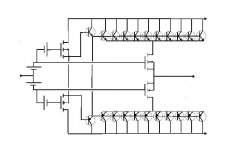
Have you built or tried this kind of outputstage ???? I got the ideas from some friends some months back and have been messing with this on and off, but now I want to sit down and get it going properly.
VR502 is actually a vbe multiplier, I have it as a resistor just to play around with the currents a little, the mosfets are very high power verticals. Herein lies the problem, BJTs and mosfets dont have same temp coefficient.
No, I didn't tried it. By looking at your schematic one can see that Gate and Drain of output FETs are on almost same potential and I don't know if that was your intention.
ostripper said:I do not use my stuff either light or intermittant.
Me neither.
Hi Ostripper! Finally, I got back on track to build your FA1. Today, I bought an amplifier enclosure for it. Next week or so, I'll pretty it up a bit, since its "around" 60 or 70 years old. Nice red stuff with a flip top. http://www.diyaudio.com/forums/showthread.php?postid=1770024#post1770024
What do you think of it? Is it suitable?
The wood is good for temp.. you might want to line it with
aluminum flashing if you want permanance.
I want to move up to a real metal box..
http://www.par-metal.com/
these guys in NJ have by far the best price and materials
and will customize it real cheap. Bud and hammond are
the only others , bud on mouser sells a 19x 17 x5 WITHOUT
the top and bottom for 57$ and sells the missing parts for
50$ more....so no real deal..
OS
Attachments
ostripper said:The wood is good for temp.. you might want to line it with
aluminum flashing if you want permanence.
I want to move up to a real metal box..
http://www.par-metal.com/
these guys in NJ have by far the best price and materials
and will customize it real cheap. Bud and hammond are
the only others , bud on mouser sells a 19x 17 x5 WITHOUT
the top and bottom for 57$ and sells the missing parts for
50$ more....so no real deal..
OS
Will reinforce. Thanks again! 😉
Um? How much heatsink? And, do I need a separate heatsink per each board so it doesn't do "hot in the middle?" I have a pair of 0.8 C/W (4.5x4x2 inches).
And, do I need a separate heatsink per each board so it doesn't do "hot in the middle?"
I use 2 /P4 thermaltake heatsinks per side (actually 2 amps on
a 13" "L" bracket bolted to 4 heatsinks) , with this ,biased at
75mA per device (8 total) , it runs cool to slightly warm at
normal to slightly loud (80+W peaks). the only time
it ever became scary was when I had a party in the summer
(40C) and forgot to use a little forced air.(80mm PC fans)
It never blew up
 , but you could not touch the
 aluminum. Those were the first amps I built, and even with
that abuse they still play.. 🙂
When I get the fancy case.. 2- 120mm fans and a PWM controller
like on my C2D pc will be the rule..(just in case)
BTW .. tonight, I post the complete "new " frugalamp 2T..
you might like this one better than "1" (easy ,low device count,
much better specs)
OS
Nice purdy board...
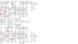
Killer circuit.. actually a modified ,simpler FA3.
Strange , you sub a mpsa42 for one of the LTP trannies and it stays balanced (also sounds exactly the same) ,maybe that's why
the APT amps spec'ed so good after 10 years.
ALL artwork is in..
http://71.203.210.93/pdf1/Electronics/Projects/Audio_amp/Frugalamp/FA2T/
File is FA2T_FULL_PCB.rar (1.58megs) 1200 DPI perfection.
MUCH better than 1 or 3.. 🙂 🙂
OS
An externally hosted image should be here but it was not working when we last tested it.
Killer circuit.. actually a modified ,simpler FA3.
Strange , you sub a mpsa42 for one of the LTP trannies and it stays balanced (also sounds exactly the same) ,maybe that's why
the APT amps spec'ed so good after 10 years.
An externally hosted image should be here but it was not working when we last tested it.
ALL artwork is in..
http://71.203.210.93/pdf1/Electronics/Projects/Audio_amp/Frugalamp/FA2T/
File is FA2T_FULL_PCB.rar (1.58megs) 1200 DPI perfection.
MUCH better than 1 or 3.. 🙂 🙂
OS
ostripper said:When I get the fancy case.. 2- 120mm fans and a PWM controller
like on my C2D pc will be the rule..(just in case)
BTW .. tonight, I post the complete "new " frugalamp 2T..
you might like this one better than "1" (easy ,low device count,
much better specs)
OS
PWM controller? Those can sometimes add a buzzy noise to your fans. Howabout a pair of Coolermaster fans and the bimetallic thermostat thingy out of an attic ventilator controller from the hardware store? That way, its always really quiet. Well, maybe I'm kinda simple. The spring is easier for me. 😉
I like the new amp a lot!!! It has much of what I'd asked for. I'm still trying to read the diagram (I'm still learning to "model" in my head), but so far, I can "see" some of what it does. Brilliant!
I do have a question. Can you do 47k input impedance? Or, maybe an option for that?
By dwb-PWM controller? Those can sometimes add a buzzy noise to your fans.
Yes , they can ..but that is if you do it wrong.. Use a separate
regulated supply for all your control circuitry (fan, dc protect,
soft start), route fan supply lines with shielded 2-conductor cable.
I like the new amp a lot!!! It has much of what I'd asked for. I'm still trying to read the diagram (I'm still learning to "model" in my head), but so far, I can "see" some of what it does. Brilliant!
I think tom holman deserves the credit .. he is still alive..
http://www.diyaudio.com/forums/showthread.php?s=&threadid=70261&perpage=25&highlight=&pagenumber=4
Post #79.
I just 'modernized' it and made it simple. on his amp he
used dual supplies and diode clamps to tame overdrive.
I am cheap (frugal) , so , just less total gain (26db) and
70v rails.. you will never clip this amp without overdriving
the preamp (soundcard) - 1.77v.
More power for 4 ohm loads (6 devices) and a tad more
headroom . I have this running on my modded FA3..
very tolerant of devices...real silky smooth sound..pleasant.. 🙂
You could add any resistor to the input (across the rca jack)
100k - 47k.
OS
ostripper said:
. . .
You could add any resistor to the input (across the rca jack)
100k - 47k.
OS
Oh, I meant R2, R15, up to a little higher figure. You see, my speakers are going to need some help with the lower bass, and I didn't want to make the nfb cap larger than the power cap/2. And, its a lot easier for me if the input cap is 1uF or even half that much. So, that's kind of what the question was about.
It looks quite doable as is, but I thought I should ask about a possible 47k option.
Edit: I didn't mean any disrespect--I asked because I just don't know.
Dan, R2/ R15 affect the over all gain of the amp.. C3/R4 and
R1/C1 are the main players for LF rolloff.
With the listed values , you get -3db at 3hz (see attachment)
with 1uF for C1 , you get -3db at 7hz. So specwise
this amp does 5hz (-1db) to 100k (-1 db).
In the real world , fa3 (same components) I can "flop" my
sub back and forth at 5hz with little drop in output.
You will have no bass issues... unless you want
to power a motor servo with it.
OS
R1/C1 are the main players for LF rolloff.
With the listed values , you get -3db at 3hz (see attachment)
with 1uF for C1 , you get -3db at 7hz. So specwise
this amp does 5hz (-1db) to 100k (-1 db).
In the real world , fa3 (same components) I can "flop" my
sub back and forth at 5hz with little drop in output.
You will have no bass issues...
unless you wantto power a motor servo with it.
OS
Attachments
If memory serves, he is using a paint package... which is both scary and admirable 🙂
I love how he gets better results with this than I do with EAGLE !
I love how he gets better results with this than I do with EAGLE !
By fjr - Which PCB software are you using?
Just the lowly paint shop pro 7 (jasc) using "snap to grid"
and 4 "tubes" (custom made donuts and IC pads) ,all
component spacings are taken from the manufacturers
data sheets .
By jkeny -which is both scary and admirable
Scary ? BOOO... I have/used eagle , maybe for a lot of IC's
it would do better, but for a "outside the box" approach
(my amps) "hands on" is better..! I can layout any simple amp
in a couple hours.
The circuit is amazing (attached) talk about LTP balance,
throw a driver or anything in for one of them, it still works
and gives .005% thd20..
I am going to SMD this input stage and drive krills with it.
2 - krill OPS's and 2- these FA2T's will be built soon.. 🙂 .
OS
Attachments
by jkeny - which is both scary and admirable
OS that quote was Jaycee and not jk but I do find all your work admirable and your rate of progress astounding - thank you for your balanced and thoughtful posts on this forum - we need more like you
- Status
- Not open for further replies.
- Home
- Amplifiers
- Solid State
- The Frugalamp by OS