yes, C21 is 47uF, RC=32mS. F-3dB~=5Hz.
The LF signal content can come from any source capable of sending it.
That's why it should be filtered out before it causes the NFB cap to generate an AC voltage.
It comes down to matching the input filter to the NFB filter in that 1.4:1 ratio, or higher.
The LF signal content can come from any source capable of sending it.
That's why it should be filtered out before it causes the NFB cap to generate an AC voltage.
It comes down to matching the input filter to the NFB filter in that 1.4:1 ratio, or higher.
By Jaycee - Try KSA1381/KSC3503 for the predrivers too. This is more like the original Leach, where the predrivers and VAS devices are the same
I tried that , no difference in performance ... ksa = .42c vs Ksp=
.09c.. I'm cheap. Also the ksp has hfe 120 same as drivers..
Ft also the same... 80-100mhz.
The split "feedforward" NFB scheme is interesting .. I haven't tried
that. Prof. leach explained it clearly, I will see if this form
of comp has added benefits.
By andrew - The 1k6 between the pre-drivers limits the current to ~{0.8mA + the driver base current}.
Same as catalin , my 1k gives me about 1.5mA , which seems
to give the best THD figures.. (I tried all between .5 and 3mA).
The NFB feedback, I did it a little different (like the quasi amp)
giving me that phase reserve (attached) across a wider range
of frequencies. Changes in R9/C5 - C16 one can "shape"
the margin instead of just setting it at the unity gain intersection.
OS
Attachments
What unity gain point do you have on that graph, out of interest?
I just quickly adapted one of my schematics to triple and didn't seem to need much other than 47pF on both VAS devices.
I'm using the Fairchild drivers + outputs though, their models are better than the Onsemi ones.
I just quickly adapted one of my schematics to triple and didn't seem to need much other than 47pF on both VAS devices.
I'm using the Fairchild drivers + outputs though, their models are better than the Onsemi ones.
What unity gain point do you have on that graph, out of interest?
600k for 68pF Cdom , 880k for 47pF , 39 p starts ringing
on SW 🙁 .. (1.05Mhz BTW)
The RC shunt between LTP collectors reduces UG by 100k+
but seems to make for better stability (less ring) into cap.
loads.
who create 1-5hz? ;apologise for offtopic ostripper !
"any source capable of sending it"
Please Andrew tell what source is capable to send an signal in normal function of the amp of frequency by 1->5hz .
I am very curious .Your response is fuzzy .
On the other hand signals like 1-15hz is not good for amp so it is good to limit the lower frequency; and if we put an signal between 1-5hz(my case) he will be attenuated and be present with unitar gain at the output ! I we supose that we are introducing 1vrms of music signal and andrew comes with "noise" (uV,mV),1-5hz (from an earthquake 😀) at the output will be present 33Vrms(music) and the same little uV,mV.If we compare uV,mV with 30-40V what distortion we hear 🙂.
I did a lot of tests and can't get 1-10 hz noise from anywhere.
I apologize for ostripper because we are offtopic of his thread .
AndrewT said:yes, C21 is 47uF, RC=32mS. F-3dB~=5Hz.
The LF signal content can come from any source capable of sending it.
That's why it should be filtered out before it causes the NFB cap to generate an AC voltage.
It comes down to matching the input filter to the NFB filter in that 1.4:1 ratio, or higher.
"any source capable of sending it"
Please Andrew tell what source is capable to send an signal in normal function of the amp of frequency by 1->5hz .
I am very curious .Your response is fuzzy .
On the other hand signals like 1-15hz is not good for amp so it is good to limit the lower frequency; and if we put an signal between 1-5hz(my case) he will be attenuated and be present with unitar gain at the output ! I we supose that we are introducing 1vrms of music signal and andrew comes with "noise" (uV,mV),1-5hz (from an earthquake 😀) at the output will be present 33Vrms(music) and the same little uV,mV.If we compare uV,mV with 30-40V what distortion we hear 🙂.
I did a lot of tests and can't get 1-10 hz noise from anywhere.
I apologize for ostripper because we are offtopic of his thread .
what source is capable to send an signal in normal function of the amp of frequency by 1->5hz
warped vinyl maybe.. I can also do 1-5hz with my VST synth😀
If the low frequency is at the speaker they will distort the sound anyway
OK!
but...
On the other hand signals like 1-15hz is not good for amp so it is good to limit the lower frequency; and if we put an signal between 1-5hz(my case) he will be attenuated and be present with unitar gain at the output ! If we supose that we are introducing 1vrms of music signal and a signal"noise" (uV,mV),1-5hz (from vinyl,etc ) at the output will be present 33Vrms(music) and the same little uV,mV.If we compare uV,mV with 30-40V what distortion we hear at that power.I think that to all speakers it'not good to put so low frequencies.They can not reproduce and we can not hear .If those low frequencies it will be present on speaker they will distort the sound anyway !
Hi Catalin,
you are convinced that you cannot get extreme LF signals through your system and that you don't want to amplify these unwanted signals.
Then swap the input filter frequency and the NFB filter frequency.
Make the input F-3dB=5Hz and make the NFB filter frequency F-3dB=1Hz.
Your amplifier will still have the same LF passband and it will operate better because the input filter sets the passband.
They can not reproduce and we can not hear .If those low frequencies it will be present on speaker they will distort the sound anyway
I DO have a sub that can do 1-2 hz (-10-12db) ... I can see it.
No big issue , I simmed both the 220u and 47u and at 3hz
very little output swing with either .47u/680R
not bad at 4hz. at 2 hz both do the job (vinyl warp <1hz).
I have seen some HT content (chronicles of riddick) with 10-15hz
content 😱 It gives sense of impending doom
 and
andthe peerless 12" CAN reproduce it!!!
Attachments

ostripper said:
I DO have a sub that can do 1-2 hz (-10-12db) ... I can see it.
No big issue , I simmed both the 220u and 47u and at 3hz
very little output swing with either .47u/680R
not bad at 4hz. at 2 hz both do the job (vinyl warp <1hz).
I have seen some HT content (chronicles of riddick) with 10-15hz
content 😱 It gives sense of impending doom
the peerless 12" CAN reproduce it!!!
The lowest frequency for vinyl warp should be about 1.8Hz.
The lowest frequency for vinyl warp should be about 1.8Hz.
Think about it.. you did the math in reverse. 12" record only goes
33 RPM - 1 turn every 1.81 seconds 1/1.81=.55 hz.
45rpm = 1.33 turns/sec 1/1.33 =.75hz
A theoretical 60rpm (1rps) LP would have a warp freq. of 1.
OS
I don't give up 😀
andrew I still think that you make much fuzz about the 1-5hz "band".Remember that this is at -3db.My oppinion is that we are going offtopic and without sense .If you can argument those things mathematical with real life measures I will change my cap 😀.
I want to say that if we put 1-5hz(noise,signal with low amplitude) at input modulated by music signals at the output will be:
1. in your case that noise attenuated by the input filter will be amplified by gain of amp;
2.in my case the noise if it pass by the input filter will pass at the output with an gain close to 1 !!
1.Let's take the example of FA2.At input we have 27k,2.2u so the f=2.69hz.The nfb have 1k+220u about 0.7hz. Assuming a "noise" at input 1.5hz and 2mV.In the input filter will pass only -6db(1mV,2 times attenuated) because at 2.69hz it is attenuated with~ -3db.The noise frequency 1.5hz,at least 0.7hz(zero for nfb and pole for closed loop gain amp) will pass at the output with Vlowf*(1+27k/1k) ie we will have 28*Vlowf at output=28*1mV=28mV.Vlowf is the amplitude of the low noise passing attenuated at the output of the input filter ie Vnoise/2, (-6db).So in your case we have 28mV at 1.5hz.
2.In my case input filter at low frequency set pole at 0.16/(22k*4.7u)=1.54hz.We put like case1(fa2) a 2mV amplitude at input.This noise after the input filter will have a -3db gain because we have pole at that freq.;So here will be 1.41mV (2mV/sqrt(2)=1.41) .The second pole of the amps gain is set by the zero in the feedback network(680+47u).Here pole in the amps transfer function it is at 0.16/(680*4.7u)=5hz.The noise frequency 1.5hz and 1.41mV will be "gained " with 1.So at the output we will have ~1.41mV of noise .
In those 2 cases I neglect the -3db of the zero feedback and pole in closed loop.The differences with this neglection are the same.
If still are missunderstanding I can put an mathematical transfer function in s. H(s) 🙂 .
Wich case is better ? 28mV or 1.41mV of noise 😀
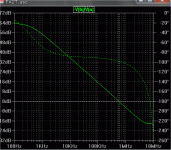
Are you hearing frequencies <20 hz ??
Not on music.. most mp3's don't have <30hz content. But,
on SOME movies subsonics are there. You can't hear.. it
just shakes the room. so , a rolloff at 10-15hz -3db at 6hz
is kind of useful when the music system is also the HT. 😀
It doesn't help to bandpass the 20- 30 hz either..
(attached)
OS
Attachments

And if you want to produce the effect of an earthquake with magnitude close to the real life sounds you must do it at full power amps . 😀
Do you use for that waves the amps ?
I build amps just for listening .
Do you use for that waves the amps ?
I build amps just for listening .
And if you want to produce the effect of an earthquake with magnitude close to the real life sounds you must do it at full power amps
The sub out put of that EQ is split between my "listening"
speakers (2 -100watt "blameless" amps/sony 3-way) and my
200 watt sub amp. When I do music I get rid of the "peak"
at 30hz (another preset) and chill (no earthquakes)😎
BTW a real dinosaur/jetplane/ earthquake takes 200w or
more.. thats why I need the FA2 "beast" 80-0-80 800VA
MOSFET.. I will only build 1 .. for my listening the little triple
will do..
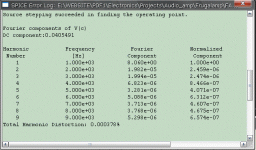
Andy C. gave me a new sine generator and distortion on
the triple is LOW.. (attached)
😎 😎
OS
Attachments
I don't understand why for an amplifier who plays only low freq for subwoofer must be an very low distortion super amp...,music in films is played not lossless ...etc;
Less distortion in triple and double final stage gives the sziklai configuration <0.0001% .I calculate and simulate and that configuration is loading verry little the vas stage unlike the ef .At the same current at output the sziklai absorbed a little current at the input unlike EF.Beside that it have gain and negative feedback(low distortion and higher bandwith). All that improves the thd and dinamic distortion,intermodulation distortion and slew rate.
Just my opinion .I like those discutions .We can learn a lot .
Cheers !
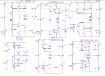
Attachments
ostripper said:
Think about it.. you did the math in reverse. 12" record only goes
33 RPM - 1 turn every 1.81 seconds 1/1.81=.55 hz.
45rpm = 1.33 turns/sec 1/1.33 =.75hz
A theoretical 60rpm (1rps) LP would have a warp freq. of 1.
OS
Not quite in reverse. I got to the 1.8 and didn't take the reciprocal. You are correct.
By catalin - I don't understand why for an amplifier who plays only low freq for subwoofer must be an very low distortion super amp...,music in films is played not lossless ...etc;
I guess I could build a project 68... http://sound.westhost.com/project68.htm
But that is a "hack" circuit , best for lamers who are too lazy
to design their own. It would work , but I am not going to hook
my $200 peerless sub to such a primitive circuit.
I've seen subs even run off of bridged chipamps, but that is a lamer
way out as well. I think a "real" amp , at least a quasi mosfet
nmos 350... good amp - NMOS 200 sounds very good with subs..http://www.adam.com.au/cgpap/QuasiWeb/index.htm
Even this would be slacking (DIY = do it YOURSELF) so..
the beast... Earthquake/ shaking killer amp...
An externally hosted image should be here but it was not working when we last tested it.
By catalin - Less distortion in triple and double final stage gives the sziklai configuration <0.0001% .I calculate and simulate and that configuration is loading verry little the vas stage unlike the ef .At the same current at output the sziklai absorbed a little current at the input unlike EF
I am very interested in your sziklai Op stages , but was told
of instabilities associated with them. Which of the ones
you posted sound the best, load the vas the least, and are the
most immune to load impedance variations.??😕
Also any insight to how you T-comp the stages would be
helpful..
OS
ostripper said:
I guess I could build a project 68... http://sound.westhost.com/project68.htm
But that is a "hack" circuit , best for lamers who are too lazy
to design their own. It would work , but I am not going to hook
my $200 peerless sub to such a primitive circuit.
I guess I'm lame...🙂
That was the very first working amp that I ever built - it ran flawlessly for nearly 2 years before I stripped it to build a bigger model.
Important to remember that a sub operates at a very narrow band width and doesn't need to be ultra fast or ultra low distortion, it NEEDS to be stable and durable. Rod's "primitive" circuit is just that. Anything more is a wasted effort.
Attachments
- Status
- Not open for further replies.
- Home
- Amplifiers
- Solid State
- The Frugalamp by OS