
One ounce copper and 2oz copper vias and traces conduct heat differently during soldering. I‘m used to soldering 2 oz copper, so that’s what I ordered. There is a rhythm to the process. The Universal Power Supply from the store is made with 2 oz copper, as are the other channel boards I have assembled.
That said, many builders have ordered PCBs with 1 oz copper and have been happy with those.
That said, many builders have ordered PCBs with 1 oz copper and have been happy with those.
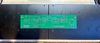
Just loading the 2 boards for the Diamond Buffer version into my JLCPCB cart, and I notice it shows them being different lengths.
Left = 259.21mm x 61.21mm
Right = 255.78mm x 61.21mm
Not that it worries me, but is that correct TA? I assume the mounting hole centres are the same on both boards.
I will go the 1 ounce copper route.
Left = 259.21mm x 61.21mm
Right = 255.78mm x 61.21mm
Not that it worries me, but is that correct TA? I assume the mounting hole centres are the same on both boards.
I will go the 1 ounce copper route.
@TungstenAudio
2 questions:
Does the F6 Diamond edition allow for higher voltage rails (more than +/25 volts or so) or will that potentially violate the SOA of some of the transistors used in the Austin buffer stage?
Is it better to locate the additional caps after the cap multiplier next to the main F6 pcb board if space allows? I am genuinely asking. You are the first to have mentioned this improvement in a Class A amplifier as opposed to Class AB where I usually try to add additional cap banks after the main supply (for an application, see Nelson Pass’ AB100 design where caps are locally placed, both physically and electrically to the main board). You are also the first to have mentioned this use especially with a cap multiplier already in place. So obviously it has nothing to do with lowering ripple but may have everything to do with addressing the periodic demands imposed on the supply during dynamic peaks?
Best,
Anand.
Anand, @Vunce also has used local cap banks after CapMx (SLBs). I believe he is pleased with that setup.
The Toshiba TTC004B and TTA004B bipolars used in the Diamond buffer are rated for 160V. The smaller transistors are rated for 120V. So the Diamond buffer is easily capable of running on 32V rails.
The large electrolytic caps that need to be added on the output of the SLB may be located where you have space for them. I kept the wires to the SLB short.
The large electrolytic caps that need to be added on the output of the SLB may be located where you have space for them. I kept the wires to the SLB short.
The new PCBs, both sets, are compatible with the UMS mounting system. I have a set of heatsinks for the 4U x 500mm chassis. The board and Mosfet mounting holes align with the center locations.
There is a caveat: two piece heatsinks will probably need to have their inner fins dressed with a file to let the pieces fit such that the hole spacing is accurate. I needed to do that with these. Manufacturing tolerances are such that this is not uncommon.
There is a caveat: two piece heatsinks will probably need to have their inner fins dressed with a file to let the pieces fit such that the hole spacing is accurate. I needed to do that with these. Manufacturing tolerances are such that this is not uncommon.
Attachments
I will have a couple pairs of F6 Diamond boards available, 2oz copper in blue. Probably best to keep shipping within the USA.
PM me if interested.
PM me if interested.
Hey Vunce, don't tell me you listen to Heavy Metal as well on your Heavy Metal Class A amps. With your weather turning cold over there time to warm up the house with your amps.Maybe overkill, but with the heat generated by class A builds I sleep better knowing Heavy Metal is inside 😆.
Yes, at the original bias of 1.05A from the original circuit at +/- 24V one only needs to dissipate 50 watts per channel (this is in the DIYAUDIO F6 illustrated build guide thread). I’ve repaired a few of those on a 4U/300 heatsink and they are just warm, maybe 45 degrees C. Decent performance with IRFP240/9240.
But these 2 circuits in this thread allow for higher bias should you wish to do so, i.e. 1.6-1.8A on bigger heatsinks (primarily due to the spacing of the MOSFETS which allows 400mm chassis use). More Class A power for 4 ohm loads before it KLUNKS to Class AB. Moreover, with the F6 diamond edition (not the JFET addition), you can increase the voltage rails to +/- 30V - get more power into 8 ohms and 4 ohms, plus the additional option of higher currents mentioned above. About 25% more power into 8 ohms, or conservatively, let’s say going from 25 watts to 31 watts. The amp will get MUCH hotter. Now we are talking +/- 30V @ 1.6A = ~ 100 watts dissipation. If you put that on a 4U/300, it will feel quite hot (not recommended!). But in a 4U/400 or 5U/400, it’s good.
Mine will be in a 5U/400, so it will feel warm to hot but not scorching. I’m aiming at 50-55 degrees overall on the sinks as my max. What is hot, warm or cold is all dependent on voltage rails, bias current and size of heatsinks (as well as the environment the amplifiers reside in). Easy peasy to calculate, and if you are pressed, you can also calculate what the temperature is right at the MOSFETS to be real sure, since that is what is most important.
Tungsten has experimented quite a bit with this circuit so I am going to follow his lead and build it into my NPXP. Thanks again Tungsten for the ongoing research.
Best,
Anand.
Hi TA, any further updates on your builds / testing / listening. Have you had a chance to compare the Jfet vs Diamond Buffer version. Look forward to any further thoughts from you. I have just received 2 off Jensen transformers (very quick USPS delivery from the US)- so now have to decide on what version to build first, have ordered both pcb types. Will be my kick off project for the new year. Will go the dual mono PSU route as you have done with SLB boards.
I haven't done a 'fair' comparison between the JFet vs Diamond Buffer version. The Diamond buffer went into the best chassis that I had with the best output devices that I had. The JFet version resides in a chassis that is more typical of a build from a DIY enthusiast that is newer to the game and using a Modushop chassis with IRFP048 output devices. I cheated a little with synchronous rectifiers and added the motor run caps later to hear how that would improve things.
The Diamond buffer boards will be the main experimental platform going forward. Now is probably a good time to get back to the IXTQ75N10P Mosfets that I was experimenting with earlier. These look promising as substitutes for the FQH44N10. They need a slightly higher threshold voltage to operate at the preferred bias current. The new PCBs make it easy to use a blue LED in each string to get a higher voltage for setting the bias.
The Diamond buffer boards will be the main experimental platform going forward. Now is probably a good time to get back to the IXTQ75N10P Mosfets that I was experimenting with earlier. These look promising as substitutes for the FQH44N10. They need a slightly higher threshold voltage to operate at the preferred bias current. The new PCBs make it easy to use a blue LED in each string to get a higher voltage for setting the bias.
I was digging through some of my old posts in the F6 Build thread. I found the list of part substitutions I made to the SLB boards:
I tweaked the SLB components a little to use lower VceSat bipolar transistors, and got good stability in the CFP. Here is a list of the changes that were made to the SLB, referenced to the SLB-APRIL-11-2019 schematic:
R1, R2: 18 Ohm
C7, C8, C13, C14: SLPX183M050H9P3 (18,000 uF, 50V)
Q9, Q11: KSC2690AYSTU, KSA1220AYS
Q10, Q12: MJW1302AG, MJW3281A
R17, R18: 1.8 Ohm
The transformers I used were the Antek AS-3222, which gave me +/– 26V power rails with 1.85A bias current.
Thanks for the reply TA, looks like it might be the Diamond Buffer version. Thanks as well for the updated SLB mods you implemented.
Hi again TA, had a quick scan of this thread looking to see if it had been mentioned - did you match any of the input transistors on the Diamond Buffer build?
I have not specifically matched the input transistors for the Diamond buffer. I ordered the cut tape version of those transistors, however, so they are likely to come from the same production run. Seem to be close enough.
Similarly, I pulled four FQH44N10 Mosfets from the end of their tube. No explicit matching other than sharing a common lot code.
Similarly, I pulled four FQH44N10 Mosfets from the end of their tube. No explicit matching other than sharing a common lot code.
- Home
- Amplifiers
- Pass Labs
- The F6 Revisited