The zeners are not needed when the LEDs are installed. I will eliminate them in the next version.
OK, that is now clear, thanks again. I also note you used side adjust trimpots on this version, makes sense if the pcb is mounted vertically on the heatsink.
Part numbers for that pot would be 652-3266Z-1-502LF or the cheaper 652-3296X-1-502LF from Mouser - both with inline pins.
Part numbers for that pot would be 652-3266Z-1-502LF or the cheaper 652-3296X-1-502LF from Mouser - both with inline pins.
Last edited:
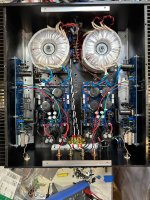
Installation into the larger F6 chassis has become more complicated that I was expecting. This chassis is 400mm deep, as necessary for a dual-mono build with flat mounted power transformers. The heatsinks had no pre-drilled mounting holes. With the original F6 boards from the store, I located the boards to keep the Mosfets more centrally located on the heatsinks. This might not match with standard mounting hole locations on Modushop heatsinks.
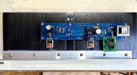
Now the new boards can still do this, but with different PCB mounting hole locations. The Jensen transformers are not as far back, but are hopefully Ok. I have taken the expedient route of just using the soldered Mosfets to hold the boards in place, with a rubber strip underneath the upper mounting studs to prevent shorts. If the closer proximity of the Jensens to the power transformers becomes an issue, then there will be other measures to consider.
Now the new boards can still do this, but with different PCB mounting hole locations. The Jensen transformers are not as far back, but are hopefully Ok. I have taken the expedient route of just using the soldered Mosfets to hold the boards in place, with a rubber strip underneath the upper mounting studs to prevent shorts. If the closer proximity of the Jensens to the power transformers becomes an issue, then there will be other measures to consider.
Attachments

A bit confused here, are you building the original but modified and then your newer design with the diamond buffer - perhaps to compare?
This is a pair of the new boards going into the chassis that had my old modified boards inside. I want to hear how the new boards sound with the power supply.
TA,
If I understand you correctly, the 2 screws through the 2 MOSFETs are holding the PCB in place, as none of the other PCB screw holes are matching the diyAudio store PCB that you had earlier?
The Jensen transformer is some added weight to the F6 PCB, but hopefully you have it under control and the PCB has no tendency of tipping forward?
You have that correctly. There is some support from the existing mounting studs, insulated by rubber strips. So the boards are actually fairly secure. I wouldn’t turn the amp on its side and shake it vigorously, but that should go without saying.
I have both boards installed in the chassis. One of them is presently going through its first power-on with bias and offset setting. It has been much easier so far than the previous set. The NTC bias current circuit is observable as the side warms up. Having the green LEDs all soldered into the PCB makes a big difference.
I have both boards installed in the chassis. One of them is presently going through its first power-on with bias and offset setting. It has been much easier so far than the previous set. The NTC bias current circuit is observable as the side warms up. Having the green LEDs all soldered into the PCB makes a big difference.
The bias current is effectively stable after half an hour.
Next up is the other channel. Then both channels get a cold start and final check with the lid resting on top.
Keeping the Mosfets centered on the 400mm heatsink was the way to go.
Next up is the other channel. Then both channels get a cold start and final check with the lid resting on top.
Keeping the Mosfets centered on the 400mm heatsink was the way to go.
Yep, slow and steady wins the race. We look forward to your listening observations once built and tested. Especially interested in your thoughts and differences between the Jfet and Diamond Buffer versions.
Yes, most of us have already done the LED modification to our F6’s but we are still holding on to the original JFET input buffer stage. The Austin diamond buffer would be a welcome change of experimentation. Always looking forward to your implementations, Tungsten!
Best,
Anand.
Best,
Anand.
Am I correct in assuming that the 400mm deep chassis is the Deluxe 5U chassis which can be purchased from the DIY Audio Store? This would avoid having to order directly from Mod-U-Shop in Italy (a 400mm deep 4U chassis is not available from the DIY Audio store).Installation into the larger F6 chassis has become more complicated that I was expecting. This chassis is 400mm deep, as necessary for a dual-mono build with flat mounted power transformers. The heatsinks had no pre-drilled mounting holes. With the original F6 boards from the store, I located the boards to keep the Mosfets more centrally located on the heatsinks. This might not match with standard mounting hole locations on Modushop heatsinks.
Now the new boards can still do this, but with different PCB mounting hole locations. The Jensen transformers are not as far back, but are hopefully Ok. I have taken the expedient route of just using the soldered Mosfets to hold the boards in place, with a rubber strip underneath the upper mounting studs to prevent shorts. If the closer proximity of the Jensens to the power transformers becomes an issue, then there will be other measures to consider.
^ That's not a Modushop chassis in the picture, I don't believe.
TA, If it was mentioned earlier, and I missed it, apologies. Are the boards UMS compatible?
TA, If it was mentioned earlier, and I missed it, apologies. Are the boards UMS compatible?
The boards, both JFet and Diamond input, are UMS compatible. The JFet boards were installed in a Modushop 4U Deluxe "jack of all chassis" for testing.
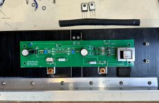
The chassis that is currently being used for testing the Diamond input buffer boards is not a Modushop product. It was drilled and tapped to take the store F6 boards. Given the new Mosfet locations, I could either bolt the Mosfets in the center locations, or bolt the boards to the heatsinks, but not both.
There is probably a way to add a couple extra mounting holes to the Diamond buffer board to better accommodate 400mm deep heatsinks, either Modushop or others.
- Home
- Amplifiers
- Pass Labs
- The F6 Revisited