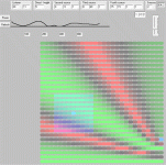
There you go. The key is what happens before this energy curve is smoothed. It is modal. Here are some room cross-section calculations on modes in the baffle region. These are to show location dependence and frequency dependence. Averaging the modes may result in chosing to use 3-4dB of compensation. In anechoic conditions, it would be 6dB.The increased energy then gets bounces back into the room. The above shows the average room corrected response.
Room gain refers to static pressurisation. Not practical in a real room.
Attachments

Room gain refers to static pressurisation. Not practical in a real room.
Not disagreeing for the sake of disagreeing. There is really so such thing as room gain, but it is basically gain of the speaker as it approaches spherical radiation. In the same way that tweeters have effectively negative gain (and midrange drivers in the upper range) when they start to beam. I think we all know what is going on, so using the term 'room gain' is really just semantics - but we all use semantics every day in some form or other and nobody disagrees.
But whatever we call it, it is actually a good thing for LF.
What I find more interesting is that running many speakers desgned for small rooms and then playing them in large rooms (halls?), they can sound very flat and disengaging. You end up with a energy hole typically about 200 Hertz and maybe lower, where the designer did not go the full 6dB diffraction loss compensation and the lack of room boundaries coming in at enough frequencies and lack of 'room gain' to the listener. In one case we used a small 10" subwoofer and rolled it off above 100 Hertz and it helped almost magically. The main speaker went down to only 50Hz - a trick, but it saved the day. This was in August last year at Sydney Audio Club held at the Epping (yuck) venue.
August 2019 - Sydney Audio Club
Last edited:
I'd have to say, I'm struggling to understand much of that post Joe.
Well, if you wish, let me break it down for you. Where is the hiccup? If some driver radiates into half space and then full space at a different frequency (LF), then you are putting a lot more energy into the room (at LF). If on the other hand, a driver starts and usually at higher frequencies, to beam and less off axis energy/response is measured, then it is clearly less than half space and then negative energy is radiated relative to the half space of a forward aimed driver. Is that clearer? It's actually textbook stuff.
No, it won't. The energy density will be lower at lower frequencies.If some driver radiates into half space and then full space at a different frequency (LF), then you are putting a lot more energy into the room (at LF).
Link, please?negative energy is radiated relative to the half space of a forward aimed driver. Is that clearer? It's actually textbook stuff.
No, it won't. The energy density will be lower at lower frequencies.
I think we are talking about different things, so I will leave it there. Try read Martin Collom's tome "High Performance Loudspeakers" - I have sixth edition, I see there is now a seventh edition.
https://www.amazon.com.au/High-Performance-Loudspeakers-Martin-Colloms-ebook/dp/B00D4NDGO2
If some driver radiates into half space and then full space at a different frequency (LF), then you are putting a lot more energy into the room (at LF).
It depends.
Does it put more energy into the room because it is radiating at a lower frequency? Well, maybe, and it depends on the underlying assumptions. If the SPL is the same at the two frequencies, the sound power and intensity will be the same.
Does it put more energy into the room because it is radiating into 4pi instead of 2pi? No.
At 2pi, the sound is radiated into the front hemisphere (in "front" of the baffle). At 4pi, the sound is radiated into the full sphere. The sound energy coming out of the driver and into the room is the same if everything else is the same.
Wasn't the idea of room gain in typical listening rooms debunked?
Not at all, as you move below the room's fundamental resonance you will get some amount of "gain" assuming it is a room in the sense of 4 walls (w/floor&ceiling), this is despite most architecture with room's having very lossy chacteristics. (..and even in the US where room's are likely that, there are more than a few in the US with basements that are far less lossy and where the listening system is setup.)
Look through Stereophile's measurements, both the anechoic measurement and then the in-room measurement: often the room's that are being measured in are modest in size with modes only going as low as 30 Hz - which is still contributing to freq.s lower than this (..pass-band effect), but not in the amount that would provide the gains you'll often see.
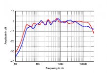
The very first loudspeaker that "popped-up" on Stereophiles front page listing: Sonus Faber Olypica Nova 1 (red curve in-room):
Attachments
Last edited:
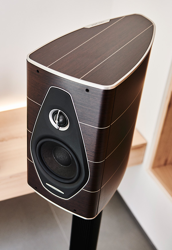
Sonus Faber Olypica Nova 1
I just read that review. The assymetric enclosure made of pressed veneers to make a plywood — similar to the B&W Nautilus bass boxes.
dave
Definitely makes for a stiffer panel when it's done like that with a metal "skeleton". (..though I was expecting something higher in freq. - it might not be that stiff after all.)
They should have spot damped the interior with some floating weight.
They should have spot damped the interior with some floating weight.
Attachments
Last edited:
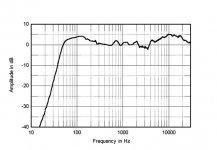
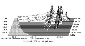
The red/blue curve appears to show mostly modal type behaviour. What was that fundamental frequency?
gedlee said:I am not a strong proponent of room gain because it requires a very well sealed room and I haven't seen any of those yet.
I recently did an extensive set of measurements in my listening room which is far far better sealed than most - its sound proof and any leaks are sound leaks. (I'm going to document the procedure for setting up multiple subs. ) Well there was no sign at all of any room gain - nada - nothing.
Does it put more energy into the room because it is radiating into 4pi instead of 2pi? No.
Actually, come to think of it, that is correct. I did not have any decent sleep for near 48 hours and should have made that point myself. But I was right about the beaming, but here in practice, here we are talking above 1KHz. Also, the boundary at LF becomes +10dB, but at way too low frequencies, but up to 8dB has been noticed (measured with pink noise in-room) depending on speaker and position. So at least in theory it is greater than the 'step' that happens above that. The Elsinores takes advantage of this. I ask, what is my main job? Theory or making things just work? And in what kind of room? Honestly, 2Pi versus 4Pi discussions are not exactly what speaker designers talk about. They will talk about what the mic picks up and what to do with that data. Practical considerations outweigh theoretical discussions (stuff they looked at years back when they got into the 'business' of speakers) and getting on with it. The theory can look after itself at that point. I like both sides, I just put more emphasis on one rather than the other, as do speaker designers who actually make stuff work.
Edit: To quote John Curl loosely, you can design speakers by way of theory, and he knows the theory, but he says he is no good at designing a really good sounding speaker and that he has tried - he now leaves that to others and sticks to electronics. That is likable honesty.
Last edited:
I was expecting something higher in freq.
I too was surprided that those were so low.
dave
The red/blue curve appears to show mostly modal type behaviour. What was that fundamental frequency?
I don't know what JA's room is (..and I'm sure he's changed it over the years). 😱
On the other hand, I don't see anything below 30 Hz that looks like a mode contribution. Do you? Note: I'm not saying there isn't any contribution at lower freq.s from a mode (say, at 31 Hz - that does look like a mode), but rather that it doesn't explain the very clear difference in amplitude between the two results at freq.s lower, and considerably lower than that.
The in-room response at 15 Hz is showing -25 db, the nearfield result is likely about -45 db. That's not only a large difference, there is no "peak" (or "null" for that matter) shown in that octave (between 15 and 30 Hz).
As for what Earl remembers from a measurement a long time ago that he hasn't provided at all, nor any condition for that measurement. ..well, let's just say I'll take the largest source of actual comparative data available showing these differences over many speakers and many rooms for more than 30 years. 😉
Last edited:
I too was surprided that those were so low.
dave
It could be that the metal is more of veneer than a structural element. In other words I think the result is just like fairly thin-wall plywood (without any of the panel "breaks" you'd expect if the design had a segmented metal spline for attaching smaller panels to it). Given the size of the speaker it's very similar to what I would expect for "monolithic" 1/2" ply. 😱
Cool looking, but not something to take as good structural design (..at least not without floating heavy panels inside the enclosure: and if that was the case I'd probably make it closer to 1/4" ply for easier damping).
Ah ah, two with one catch:
" Although the enclosure doesn't have any parallel walls, which should minimize internal standing waves, it didn't appear to be as well-damped as I was expecting from the constrained-layer design. "
Standing waves and CLD have an impact even at Stereophile!
" Although the enclosure doesn't have any parallel walls, which should minimize internal standing waves, it didn't appear to be as well-damped as I was expecting from the constrained-layer design. "
Standing waves and CLD have an impact even at Stereophile!
Opinions on Elsinore cabinet adjustment....
Hopefully this gets some responses 😀
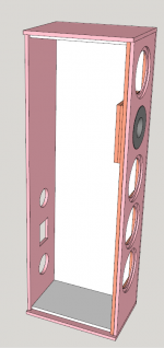
I have been looking into a few MDF alternatives, some less promising than others. 1/4 Aluminum will need 3-4 4x8 sheets, blowing the value engineering budget, but the after drawing up in 1/2" aluminum AND some 1/2" MDF interior lining/dampening, I have a model that keeps the volume pretty close to the original, without as much internal bracing...
The attached shows 1/2" aluminum skin around the entire enclosure.
The sub front panel is also 1/2" aluminum.
Behind the tweeter is (2) 1/2" MDF damping.
The top, bottom and both sides also have 1/2" MDF for additional dampening.
SO, No center brace, I may add by building up 1/2" MDF, but my thinking is the 1/2 aluminum is 9 times stiffer than ply (learned from someone else in these forums) and adding the MDF to the largest panels should deaden things further.
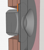
What Im not thrilled with is the section of thin aluminum behind the tweeter,
and have a plan... Brownells bedding compound. Tape off anything you dont want permanently filled, apply release compound to the rear of the tweeter, which drys microscopically thin, and set tweeter in to bedding compound. Once cured, the tweeter should have the most perfect fit possible. Reading Joe's posts, I learned that this should be one of the stiffest areas to ensure the best sound...
The volume of this enclosure is within 76 Cubic inches of the original.
That's 8.7 x 8.7 x 1, so overall very close IMO... I can still line interior with MLV or may be to vertical ribs down the center of the sides.... I kept the width of the cabinet as close as MM to inch could allow.
Cost, for 1.5 sheets of 4x8x1/2" 5058 should be about $1,500 or so. Im unsure of how much the waterjet service will be, but would never take this on without that. I will have to mill out the recesses in the front panel, but have used a router on aluminum before and with thin enough passes, steady hands and some lube have gotten amazing results....
I hope to have as dead of a box as I can. With a bit more info I think I can make my final decision on this or a more typical approach...
So, my questions to those with waaayyy more knowledge than me,
Is not having the center brace a deal breaker in your opinion ?
Things making me think long and hard,
Im figuring nearly 169 lbs in aluminum per speaker, and expect at least each to be near 200 lbs!
A bunch of take home pay, quite a lot of risk, a lot of weight
Would certainly be the elephant in the room if my plot is all wrong (as usual).
Hopefully this gets some responses 😀
I have been looking into a few MDF alternatives, some less promising than others. 1/4 Aluminum will need 3-4 4x8 sheets, blowing the value engineering budget, but the after drawing up in 1/2" aluminum AND some 1/2" MDF interior lining/dampening, I have a model that keeps the volume pretty close to the original, without as much internal bracing...
The attached shows 1/2" aluminum skin around the entire enclosure.
The sub front panel is also 1/2" aluminum.
Behind the tweeter is (2) 1/2" MDF damping.
The top, bottom and both sides also have 1/2" MDF for additional dampening.
SO, No center brace, I may add by building up 1/2" MDF, but my thinking is the 1/2 aluminum is 9 times stiffer than ply (learned from someone else in these forums) and adding the MDF to the largest panels should deaden things further.
What Im not thrilled with is the section of thin aluminum behind the tweeter,
and have a plan... Brownells bedding compound. Tape off anything you dont want permanently filled, apply release compound to the rear of the tweeter, which drys microscopically thin, and set tweeter in to bedding compound. Once cured, the tweeter should have the most perfect fit possible. Reading Joe's posts, I learned that this should be one of the stiffest areas to ensure the best sound...
The volume of this enclosure is within 76 Cubic inches of the original.
That's 8.7 x 8.7 x 1, so overall very close IMO... I can still line interior with MLV or may be to vertical ribs down the center of the sides.... I kept the width of the cabinet as close as MM to inch could allow.
Cost, for 1.5 sheets of 4x8x1/2" 5058 should be about $1,500 or so. Im unsure of how much the waterjet service will be, but would never take this on without that. I will have to mill out the recesses in the front panel, but have used a router on aluminum before and with thin enough passes, steady hands and some lube have gotten amazing results....
I hope to have as dead of a box as I can. With a bit more info I think I can make my final decision on this or a more typical approach...
So, my questions to those with waaayyy more knowledge than me,
Is not having the center brace a deal breaker in your opinion ?
Things making me think long and hard,
Im figuring nearly 169 lbs in aluminum per speaker, and expect at least each to be near 200 lbs!
A bunch of take home pay, quite a lot of risk, a lot of weight
Would certainly be the elephant in the room if my plot is all wrong (as usual).
Attachments
It's still a poor-value proposition. The material is just too expensive, and overall counter-productive when used all-over the speaker.
Aluminum for the front baffle is excellent, but still a poor value proposition compared to 3/4" "edge-oriented" bamboo ply: which is extremely stiff.
Bamboo Wood Boards 3/4"x12"x8' (Choose Your Size), Cut to Ship - Woodworkers Source
Standard added-mass in the form of a few layers of hardboard (1/2") wood-glued to this panel should kill anything significant. (..unlike the other panels this is not a floating panel layering: see below.)
Note: importantly chamfer the baffle's rear so that midbass driver's aren't generating a resonance at higher freq.s due to a "tunneling" effect of a thick baffle.
Cement for that front baffle is the next step-up in value. There are many youtubes on GFRC, and you can make the mold out of MDF (and you only need 2 good baffles).
I would make sure that the tweeter is de-coupled from the front baffle, perhaps with a nice soft silicone caulk "floating" the waveguide + tweeter in place. This doesn't mean it shouldn't have it's own rigid support behind the baffle (..though it should NOT be connected to the baffle), just that the integration between baffle and waveguide + tweeter was with a lossy material to avoid panel resonance transmitting from baffle to waveguide + tweeter.
Next relevant panel is the base/bottom panel for rigid coupling to a stand/floor. It's less important though.
The other panels however should be fairly thin-wall flexible that can be easily damped with a mass damper (heavy - like 1/2" cement panel, or at least that in hardboard), and a thin layer of Green Glue between that floating panel and the thin-wall exterior panel. You can add to this with very minimal cross-bracing of just 3 points (irregularly spaced) between just the side panels. This would kill the major modes of those side panels while the mass-damper would kill smaller vibrations.
The top and rear panels are less important.. and you could do a more minimalist (no wood veneer) that simply used the same bamboo ply + hardboard (interior) for not only the baffle but also the bottom, rear, and top panels. More expensive, but not grossly so. Then make the larger side panels (float hardboard on plywood) as mentioned and use perhaps a car vinyl wrap in a color you like; Carbon-fiber or Brushed-black aluminum might complement the drivers on the baffle nicely.
Last edited:
- Home
- Loudspeakers
- Multi-Way
- The "Elsinore Project" Thread