It's an optional feature, something to do with current and voltage from the ampI am in the process of getting my parts together for an Elsinore build. Rather than wade through this entire thread again I thought it would expedite things if I just posed my question here. The crossover diagram on Joe's webpage for the tweeter has a resistor of 6R8 and a 0.47uF cap. Both are in red with no referencing number. What is their story? TIA
Paul
Sent from my SM-G900F using Tapatalk
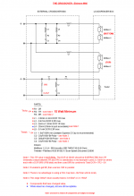
6R8 and 0.47uF is a tweeter Zobel, which mainly corrects and lowers high frequency impedance, and perhaps rolls off the top end slightly, hence sounds smoother with some amps which verge on instability.
It is connected parallel to the tweeter. No link or schematic provided, so I can't say more.
It is connected parallel to the tweeter. No link or schematic provided, so I can't say more.
Latest Mk6 schematic is at the bottom of the Elsinore home page.
Elsinore Speakers DIY
As system7 mentioned, the parts are there to flatten the rising tweeter impedance. Note that they are placed before the crossover, not parallel to the tweeter. So,when driven by a low impedance voltage source amp, the parts have no effect on the response whatsoever. However when driven by a high impedance or current source amp a rising impedance would cause the top end of the tweeter response to rise relative to the response when driven by a voltage source amp. The zobel keep the impedance flat and thus the speaker response more independent of amplifier output impedance.
Joe's comments on these parts here:
elsinore-project-thread-post#2011
BTW, the MK5 used similar impedance compensation although values were slightly different (10ohm, 0.68uF).
Attachments

I take it then that I should order and utilize these components in my crossovers as I have various amplification prospects.
Thanks
Thanks
It's best to include the conjugate so that you can drive them with any amplifier you may want without any issues. The cost is insignificant.
I take it then that I should order and utilize these components in my crossovers as I have various amplification prospects.
Thanks
Wave guides
Wave guides arrived. Look great. Thanks Joe. Now I just need to order all my parts and build the boxes. Shouldn't take more than a day or two. 🙂
Wave guides arrived. Look great. Thanks Joe. Now I just need to order all my parts and build the boxes. Shouldn't take more than a day or two. 🙂
Parts Are In
All of my parts arrived. Now I have to wait for the City to finish repaving my alleyway in order to gain access to my garage/shop. In the meantime I will layout and assemble my crossovers. I noted that several people have had problems with the tweeters having bad connections. In light of the fact that it may be some time before I actually fire up and test these speakers, would a simple continuity/resistance test tell me if my tweeters are okay?
All of my parts arrived. Now I have to wait for the City to finish repaving my alleyway in order to gain access to my garage/shop. In the meantime I will layout and assemble my crossovers. I noted that several people have had problems with the tweeters having bad connections. In light of the fact that it may be some time before I actually fire up and test these speakers, would a simple continuity/resistance test tell me if my tweeters are okay?
My experience was NOT a BAD connection, but rather a crappy and or flimsy design of the tweeter terminals. I had two of four pairs break off, and I had to solder a tiny wire to reconnect the tweeter terminal.
So during my build, of just positioning the tweeters and or soldering to the terminal I had them break off! It is definitely a design flaw!
So during my build, of just positioning the tweeters and or soldering to the terminal I had them break off! It is definitely a design flaw!
I should be more specific...and I just remembered this...it's been a little while so I didn't think of it at first.
I had to bend the terminals down in order to route them through the cut out..something ANYONE will have to do with any tweeter, and in positioning one just broke off....in fact the second one was more flimsy than the first I had this happen too...I was being careful after this had already happened to me!
I had to bend the terminals down in order to route them through the cut out..something ANYONE will have to do with any tweeter, and in positioning one just broke off....in fact the second one was more flimsy than the first I had this happen too...I was being careful after this had already happened to me!
The terminals on the Tweeter are meant to have spade terminals pushed on to them. If you attempt to solder to them (as I have) you must be very quick otherwise the enameled wire from the voice coil becomes detached internally which is repairable but very fiddly. I've had to repair a couple of them so I've learned the hard way. Spare diaphragms for the tweeter are available as a spare part. I've got one one the shelf just in case.
Folks:
I've been lurking around this thread for about two years, waiting for the stars to align. I have no speaker-building experience and only hand tools, but a friend of a friend owns a local high end furniture and wood-working business and he's interested in a pair of new speakers. He'll build the cabinets and I'll handle the crossovers and final assembly. I've already purchased the waveguides from Joe (thanks, Joe!) and the attached BOM is certainly incomplete, but I'd appreciate your thoughts on the parts I've selected so far. Many of the items on the list were selected based solely on the recommendations found in this thread; others were a wild-*** guess.
Here are a few thoughts and caveats:
We'd like this to be a "once and done" project and don't want to start swapping parts after the crossovers have been built. Once all the feedback is in, I'll post the final BOM (including the other parts we'll be using) just in case someone else might find that helpful.
Much appreciated,
Scott
I've been lurking around this thread for about two years, waiting for the stars to align. I have no speaker-building experience and only hand tools, but a friend of a friend owns a local high end furniture and wood-working business and he's interested in a pair of new speakers. He'll build the cabinets and I'll handle the crossovers and final assembly. I've already purchased the waveguides from Joe (thanks, Joe!) and the attached BOM is certainly incomplete, but I'd appreciate your thoughts on the parts I've selected so far. Many of the items on the list were selected based solely on the recommendations found in this thread; others were a wild-*** guess.
Here are a few thoughts and caveats:
1. Prices are in US dollars and are included to provide context. I'm open to other reliable sources if you have any suggestions.
2. We're looking for the biggest bang for the buck. I'm clueless as to inductor gauge and type (wax? perfect lay? holy water?) and capacitor nuances, so if a less-expensive and perfectly suitable alternative exists, please educate me.
3. Similarly, if there's a much better alternative for not too much more (or if the part I selected is simply a dumb choice), I'm very interested.
We'd like this to be a "once and done" project and don't want to start swapping parts after the crossovers have been built. Once all the feedback is in, I'll post the final BOM (including the other parts we'll be using) just in case someone else might find that helpful.
Much appreciated,
Scott
Attachments
This has all been pretty much covered. Actually not pretty much, I'd say it's been 100% covered. If you want to upgrade parts they will all be on the parallel sections of the crossover, and there are basically 3 options...2 coils and one cap....the two coils you'll be hard pressed to upgrade unless you're stupid...and the cap on the tweeter section can be upgraded.
The Supreme cap on that section is VERY HIGHLY rated. However, if you want to upgrade the cap on that section you may hear a difference.
After lost of research I decided to use the Audyn True Copper Caps. But They only had one in stock, and after buying one, they took forever to get the other one in stock. So I ended up using the Supreme's myself.
I started with the Supreme, and finely the other cap came in stock and I switched them over.
Now here's where it gets crazy.
These speakers sound amazing. Do they sound better with the Copper caps? I think so. Could you get a swore statement top the fact from me?...Hell no. You know why!!?????
Because these damn things sound so good any way!!!!!
Follow the plans use good cabinet martial...and you will be "one and done."
Clausen:
I'm not trying to make trouble and understand your apparent frustration at someone asking questions that have "all pretty much been covered," but I have read the thread (much of it more than once) and unless I'm going senile (a) no one has posted a BOM that identifies specific components and (b) I don't recall a particularly helpful discussion on inductor gauge or type. I also thought sparking a conversation on the relative merits of competing components might be helpful. In light of the foregoing, it seemed to me that a "best bang for the buck" BOM might prove useful (at least for the novices such as myself).
If you folks disagree, then I certainly understand and will back off.
Regards,
Scott
Scott - I for one am very interested in where you end up with your part choices. Please keep us posted and do update your useful spreadsheet/BOM.
BK
BK
If you follow Joe's recommendations as to crossover components you won't go wrong. C1 in the HF section of the crossover is the one place where I would spare no expense, otherwise stick to the recommendations as to minimum inductor series resistance etc and you will be fine. I originally had a Solen SCR cap as C1 and upgraded to a Jantzen Superior Z cap and was blown away by the improvement. I contacted Joe to brag about this only to find he was way ahead of me in this regard. Guess which cap he uses. Build them as specified and you won't be dissapointed.
irext:
I understand and will follow the advice that you, Clausen, Joe (of course) and others have provided. Everyone's counsel is absolutely appreciated. Not knowing the advantages of wax vs. baked wire vs. foil vs. whatever makes selecting the type of inductor very much a crap shoot; I had hoped for some guidance as to which type in which position offered the best results. Similarly, I can pick inductors based solely on their mH / R values, but thought that there might be advantages to heavier gauges as well; since no one is talking about that criterion, I guess it's not important.
The Superior-Z cap is a given at C1 and perhaps for the 0.47uF cap on the tweeter, and I'll probably use the Jantzen Cross-Cap at C2 and C4 (the alternative Z-Standard is considerably more expensive (about $80 more for the 4 caps needed for a speaker pair), and since no one is talking about it, perhaps that's a wasted expense).
Thanks for the counsel!
BK:
No sweat; I'll post the final BOM and provide some feedback.
Regards,
Scott
Hi Scott. I have experimented with more expensive inductors with much lower series resistance than specified and found no noticeable improvement (to my ears anyway). I also tried swapping C2 from a non pol electrolytic to a Jantzen crosscap. Also no noticeable change. I think foil inductors might be overkill. My advice would be to go with copper wound inductors which meet or exceed the minimum series resistance. Use non inductive wire wound resistors and caps as specified by Joe. I'll attach a photo of the crossovers I built for oZmoZis's lovely Elsinore build so you can see the various components used.
Cheers : Ian T.
Cheers : Ian T.
Attachments

Hi All,
Here in Melbourne, Chris Pierson (flawlessfabrications@gmail.com) is now able to cut out all the MDF panels to make Elsinore enclosures. Chris has just cut out a set of the Elsinore panels on his large flatbed CNC router. Feel free to email him if interested.
All the best
Steve
(Very happy Elsinore owner)
- Home
- Loudspeakers
- Multi-Way
- The "Elsinore Project" Thread