Bloody Juma.
He is always stealing my ideas.
I reckon he has a time machine or something
He is always stealing my ideas.
I reckon he has a time machine or something
Last edited:
Just a few comments.
For people who don't need gain. I reckon this is the amp to build.
For people who do need gain put a BA3B (ie Balanced BA3) in front of it?
I am going to bed
For people who don't need gain. I reckon this is the amp to build.
For people who do need gain put a BA3B (ie Balanced BA3) in front of it?
I am going to bed
I am not sure how to take that.😀
nicely , how else
(I'm always thinking in positive way .........
 )
)Just a trivial question.
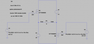
Why have they chosen 50 Ohms to ground?
Why not 1k or 10k?
ask any woman - just firmly grabbed bOOls are what count's

I told ya - input firmly referenced to gnd ( those gates are firmly tied with that range of resistance to gnd ) , while outputs are loosely referenced to gnd
in fact - those two floating supplies are loosely tied to gnd ; that's important , not outputs itself
look here : input toob
So where fck is SisSy valve stage ? Thingy in post 27 ?
(me have case of miss Babo day)
So where fck is SisSy valve stage ? Thingy in post 27 ?
(me have case of miss Babo day)
frankly , I miss him sometimes , too .
wakoo Baobabwana .......
regarding SUSY toob ....... here it is - Bastard, anyone? - Stranica 6 - Project gallery/WIKI - diyaudio.rs (pic linked here too )
I'm too lazy to find buried in da 100 Miles long thread where shunt reg is posted
maybe I'll do that later
An externally hosted image should be here but it was not working when we last tested it.
MoFo-Tron is in the article queue (Audiohobby.com) for Summer, but Fall is probably a safer bet. It may be of interest.
Keep going 🙂
Keep going 🙂
This one is even simpler. Depletion mode mosfet.
Obviously left off a few components.
Provided Id is appropriate at Vgs=0 and the Vds you want to use then this makes things a little simpler.
Not sure how tightly matched they need to be for 0 DC offset. You can always put an Elna Silmic cap at the output
Obviously left off a few components.
Provided Id is appropriate at Vgs=0 and the Vds you want to use then this makes things a little simpler.
Not sure how tightly matched they need to be for 0 DC offset. You can always put an Elna Silmic cap at the output
Attachments

Bloody Paul Hynes has a bloody time machine too.
Juma and Paul Hynes are bloody bastards
nope
I invented everything
time machine , you know - moi came back in time long before anyone was around

I invented everything
time machine , you know - moi came back in time long before anyone was around
the mofotron link on your website does not work
MR clearly wrote "in queue " etc.
- Status
- Not open for further replies.
- Home
- Amplifiers
- Pass Labs
- The dumb-O-tron