Read the last part where is amp with just single stage is unity gain amp. Screws with my head in a bad way. I need a nap.Top secret.
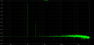
I have an even dumber circuit than this one. Just thought of it today. Should have thought of it earlier. Bloody simulates incredibly well.
As soon as I get this bastard operational I will reveal all.
From the article:
http://www.passdiy.com/pdf/Build The Amazing FET Circlotron.pdf
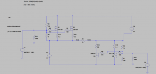
"R13 and R14 form a virtual ground for the output and help to stabilize offset drift. They lower the
output terminals to around .2 V, and the speaker doesn’t see this absolute DC."
The schematic shows the supply connected to earth through a 100 Ohm resistor. Or is it not connected to earth? Is it floating or not?
Or is that earth symbol the symbol for virtual earth?
Confused as hell.
http://www.passdiy.com/pdf/Build The Amazing FET Circlotron.pdf
"R13 and R14 form a virtual ground for the output and help to stabilize offset drift. They lower the
output terminals to around .2 V, and the speaker doesn’t see this absolute DC."
The schematic shows the supply connected to earth through a 100 Ohm resistor. Or is it not connected to earth? Is it floating or not?
Or is that earth symbol the symbol for virtual earth?
Confused as hell.
Member
Joined 2009
Paid Member
Yeah, I should have stuck with that and called it a day. 
I just need to find me a flux capacitor for the power supply. If that doesn't fix the problem, then I am sure I have got a bloody big hammer laying around somewhere.
I just need to find me a flux capacitor for the power supply. If that doesn't fix the problem, then I am sure I have got a bloody big hammer laying around somewhere.
From the article:
http://www.passdiy.com/pdf/Build The Amazing FET Circlotron.pdf
"R13 and R14 form a virtual ground for the output and help to stabilize offset drift. They lower the
output terminals to around .2 V, and the speaker doesn’t see this absolute DC."
The schematic shows the supply connected to earth through a 100 Ohm resistor. Or is it not connected to earth? Is it floating or not?
Or is that earth symbol the symbol for virtual earth?
Confused as hell.
Might ZM always say ground is relative. Perhaps the 100ohm resistors with 2mA running through them form a sort of symmetric reference point.
I was just looking at his pcb and it does indeed look like he has it connected to earth through the 100 Ohm resistor. Or at least appears to go to the chassis of his amp. I am starting to think it might be wise to use an output cap until I have it truly soughted out. Anyway I have a few ideas now hopefully have it soughted out soon.
OK might need some help soughting out how to correctly wire this up
I will upload the different options shortly
I will upload the different options shortly
Many of the tube circlotrons have a groud point near amp output, but alwsy through two equivalent resistors. I think the function of the resistors is to ensure a pretty constant refernce point, despite small differences in overall circuit. Sort of like finding balance point in PSU arrangement using transformer that its not perfectly balanced. If you were to ground directly, imbalnce in just the PSU setup could throw the balnce of the bridge off and send to DC to the speakers. You need a cap at the input and that cap needs to be grounded( I think), where to put it, I dont know. Copy Mike's amp, dropping the input fets and just grounding sk135 like he did the Jfets. Wear GLasses!😀
If the preamp has output caps then I shouldn't need an input cap surely?
I am thinking I might throw a cap at the output initially just to protect my speakers.
I am thinking I might throw a cap at the output initially just to protect my speakers.
If the preamp has output caps then I shouldn't need an input cap surely?
I am thinking I might throw a cap at the output initially just to protect my speakers.
True.
Copy Mike's amp, dropping the input fets and just grounding sk135 like he did the Jfets. Wear GLasses!😀
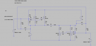
The second schematic pretty much copys Michael's grounding
Ground at feedback intersection of 100K/1K is my guess. Where is Mighty ZM? Proabbly listening to music. People these days😀
I think it should float like a virtual earth in the second schematic. If I connect it to earth I am concerned current will run to earth tripping the mains box
- Status
- Not open for further replies.
- Home
- Amplifiers
- Pass Labs
- The dumb-O-tron