Aha...
I googled the PN on the schematic and couldn't find anything, so that makes sense, twice.

I googled the PN on the schematic and couldn't find anything, so that makes sense, twice.
BTW, you probably meant IXTH20N50D...
Yes, sorry about that, (twice)...
I would be concerned about stability and applying some form of control over Iq and offset. Something more than "enough heatsink" will likely be necessary. Playing around in the area of the lower Rs could get it done but will that be detrimental to the sound? The Rs's are necessary for setting DC bias but as pictured there really is no degenerative (AC) Rs's, right? I could add some .05s or something above the .47s with minimal effect on the DC I suppose. I guess I will need to fire up the LtSpice and play a little?
N.P. actually mentioned these OP devices as substitutes for the IRF240s years ago in one of these F6 threads. But, I haven't seen where anyone has seriously thought about it?

Hello,
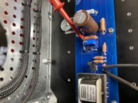
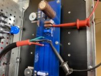
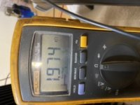
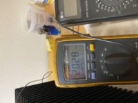
I’ve completed the build of my f6 amplifier. I tested the power supply with both channels disconnected and got 26 vdc for each channel, no problem. Before powering up each channel I wanted to set P1 and P2 trimmers in the middle of their range. Using a DVM I tried to do this but can’t seem to get a consistent reading out of all 4 of the pots, offset and bias on both channels. I made each adjustment slowly and watched for changes on the Fluke dvm as well as the LG. Both show similar responses. Both meters have new batteries. I tried changing locations for negative lead with same results. I’m unsure how to more accurately test? The pictures show high (2.03k ohms) and low readings (1.974k ohms). Please see pictures and advise.
Also, take a look at R9 as it’s larger than some of the other resistors. It’s 1/4 watt 10k but a larger size. Is that an issue?
Attachments
safest to set them to min position (close to 0R reading)
for P1 wiper to gnd
for P2 wiper to neg rail
then work first channel with second disconnected from PSU
when first done, leave it as is, proceed with second one
for P1 wiper to gnd
for P2 wiper to neg rail
then work first channel with second disconnected from PSU
when first done, leave it as is, proceed with second one
Thanks Zen Mod,
What I discovered is that the trimmers only adjust in one direction, cw or ccw. Once the maximum is reached the resistance begins to decrease. This was consistent with P1 and P2 trimmers on both channels. That was counter intuitive to me as I had assumed once a maximum was reached that rotation would need to be reversed to reduce resistance. Does that make sense?
So, I’ve set all trimmers to minimum. Specifically, offset at 13.5 ohms and bias at 91.5 ohms. Interesting to me also that offset and bias on both channels were very close. Odd? Anyway, I will proceed this afternoon with powering up both channels individually.
Thanks for your help
do not over-engineer it - set them in situ, as I said - minimum ohmic readout as explained
when you're in ballpark of minimum, that's it - good for start
when you're in ballpark of minimum, that's it - good for start
Hi!
Finished my f6 build and all was well, couple days in and now the left channel offset keeps drifting a couple of 10s of mv over time.
Right channel quickly stabilises at 6mv at the terminals, bias at 590mv
Left channel bias is around 585mv but the dc voltage at the output is not stable.
It's drifting up and down over time as well as fluctuating constantly (up to 5 tot 10ish mv) up and down within a couple of seconds, never really stabilising as well as the other channel.
Fastened the mosfets,
Bias is stable at 580mv
Measured the offset zener at 5.7 volts stable
Any tips where to look / how to fix?
Appreciate any help
thanks all!
Ellusion, do you measure with shorted inputs? Just so it's not garbage in and... out.
A bad connector can give this type of error.
A bad connector can give this type of error.
@zenmod & @strongbow60 : thank you for your replies. Sorry for my late response! (unable to be online much because of a health issue.).
Measured with input shorted. I don't know what's wrong. I guess it's ok for now, it fluctuates a couple mv in the one channel.
Before investigating further, something is troubling me more:
The sound a bit veiled / closed in. I can't imagine the sound is as it should be right now, although nice and natural, it feels like it could sound a lot better, like its constricted by something. Also missing some top end I feel. Changed out the input wires and soldered speaker wire directly to the output to bypass the binding posts. Any suggestions where to look first? boards/components, PSU, (power)wiring?
Tried biasvoltages from 580mv to 650mv, around 580mv-600mv sounds best for now. Appreciate any help!
This might be a bad solder somewhere. Have you gone through all the solder joints in the left channel? You could "top up" the solder on anything that looks suspicious, just be mindful of not overheating the fragile parts, like jfets and trimmers. The 3W source resistors take a lot of heat to do a good solder on them.
If you can, please post a well lit, sharp picture, top and bottom of the left channel board.
If you use zener diodes as voltage references it will take up to half an hour to stabilize. I did measurements with REW and I could see the distortion pattern slightly change up to 30 minutes after a cold start, and I use leds as voltage references.
The sound from my F6 is definitely not veiled, its laid back in nature but with very good dynamics and deep authoritative base, if that makes any sense 🙂
@zenmod & @strongbow60 : thank you for your replies. Sorry for my late response! (unable to be online much because of a health issue.).
Measured with input shorted. I don't know what's wrong. I guess it's ok for now, it fluctuates a couple mv in the one channel.
Before investigating further, something is troubling me more:
The sound a bit veiled / closed in. I can't imagine the sound is as it should be right now, although nice and natural, it feels like it could sound a lot better, like its constricted by something. Also missing some top end I feel. Changed out the input wires and soldered speaker wire directly to the output to bypass the binding posts. Any suggestions where to look first? boards/components, PSU, (power)wiring?
Tried biasvoltages from 580mv to 650mv, around 580mv-600mv sounds best for now. Appreciate any help!
Please take a look at this bias circuitHi!
Finished my f6 build and all was well, couple days in and now the left channel offset keeps drifting a couple of 10s of mv over time.
Right channel quickly stabilises at 6mv at the terminals, bias at 590mv
Left channel bias is around 585mv but the dc voltage at the output is not stable.
It's drifting up and down over time as well as fluctuating constantly (up to 5 tot 10ish mv) up and down within a couple of seconds, never really stabilising as well as the other channel.
Fastened the mosfets,
Bias is stable at 580mv
Measured the offset zener at 5.7 volts stable
Any tips where to look / how to fix?
Appreciate any help
thanks all!
https://www.diyaudio.com/forums/pas...a-amps-possibly-dumbest-idea-post6851970.html
I was using a lm 329 as voltage reference. After this simple change both bias and offset are very stable. This change was courtesy of picodumb and tungsten audio
I noticed that over time mine opened up a bit. Initially I felt the same as you describe but is pretty good now. Also found I needed to bump the treble a little, at least with my speakers.@zenmod & @strongbow60 : thank you for your replies. Sorry for my late response! (unable to be online much because of a health issue.).
Measured with input shorted. I don't know what's wrong. I guess it's ok for now, it fluctuates a couple mv in the one channel.
Before investigating further, something is troubling me more:
The sound a bit veiled / closed in. I can't imagine the sound is as it should be right now, although nice and natural, it feels like it could sound a lot better, like its constricted by something. Also missing some top end I feel. Changed out the input wires and soldered speaker wire directly to the output to bypass the binding posts. Any suggestions where to look first? boards/components, PSU, (power)wiring?
Tried biasvoltages from 580mv to 650mv, around 580mv-600mv sounds best for now. Appreciate any help!
Are you using all new parts, or are the electrolytics old used stock?The sound a bit veiled / closed in. I can't imagine the sound is as it should be right now, although nice and natural, it feels like it could sound a lot better, like its constricted by something. Also missing some top end I feel.
@strongbow60 : thank you for the very detailed suggestions!! I will top up everything that doesn't look pristine.
@intojazz: wow, I've read about the led solution, didn't thing it would impact sounds as described - worth a try!!
@Spe@kerBox: same feeling here: definitely need a treble boosts which helps a lot. But would love to fix it 'in-amp' haha, I'm a photographer and there's the term to not 'fix it in post' but 'in camera' - same thing here 😛
@rayma: all new -freshly from digikey.
Thank you very much all for the suggestions, I'm gonna have a go, if problem persists I'll post photo's.
Out of curiousity:
Does psu cap type have a major influence on sound character? Using CDE 380LX 35v's 15000mf now (based primarily on mr Pass usage of these caps in pass labs equipment). should I have gone with 25v perhaps? If it matters much, any alternative suggestions?
Give the capacitors a few weeks to break in, since they've likely been sitting on the shelf for a year or more.
You don't want 25V capacitors in a 24V supply, the 35V rating is much better and will last longer.
You don't want 25V capacitors in a 24V supply, the 35V rating is much better and will last longer.
Always post photos. Always. Helps with troubleshooting and/or spotting errors.
Your capacitors are fine, and no, PSU caps have almost no impact on the sound if they are operating properly and the proper spec, which yours are.
Try swapping the speaker connections. Just run your speakers ‘backwards’ (red speaker post to black amp post, etc…) and report back on the sound.
Helps with troubleshooting and/or spotting errors.Your capacitors are fine, and no, PSU caps have almost no impact on the sound if they are operating properly and the proper spec, which yours are.
Try swapping the speaker connections. Just run your speakers ‘backwards’ (red speaker post to black amp post, etc…) and report back on the sound.
@rayma - thank you, glad to hear!
@6L6 - cool! thanks! will def do, I have jbl speakers and used a lot of vintage jbls so I'm very familiar with the procedure, never done it with this combo though! gonna try asap 🙂
EDIT: @6L6 - that's not it sadly - it sounded very very wrong 😛 - worth the try though thnx!
@6L6 - cool! thanks! will def do, I have jbl speakers and used a lot of vintage jbls so I'm very familiar with the procedure, never done it with this combo though! gonna try asap 🙂
EDIT: @6L6 - that's not it sadly - it sounded very very wrong 😛 - worth the try though thnx!
Last edited:
- Home
- Amplifiers
- Pass Labs
- The diyAudio Firstwatt F6