audiosteve,
Looking at the diyAudio store 4U x 300 mm heat-sink specs, it shows 0.31 C/W, and the 3U x 300 mm heat-sink shows 0.40 C/W. So the ones you have located have a temp coefficient rating right in the middle.
40mm Heatsinks – diyAudio Store
40mm Heatsinks – diyAudio Store
Theoretically they might work, but I have never tried such low height sinks with Class A amplifiers myself.
There is also a concern about how well ventilated your space is - if it is a tightly confined space with little ventilation, then things will get hot very quickly as ambient temperature inside the space will be higher.
You are probably charting some new waters here with these low profile sinks without fans.
Last edited:
Hi Everyone,
After two years of waiting in the boxes as parts because of house move and not encouraging circumstances, finally I finished my F6 clone within a week with slow, careful steps.
Boards and Transformers and matched JFets and Keratherm isolators are from diyAudio store, PT is Antek AS4218 all other parts are from Mouser.
But I am hesitant to connect any speaker to it.
After 5 hours of bias and offset adjustment and monitorizing voltages;
Right channel offset is under 10mV with 630mV bias on 0.47Ohm resistor. During 5mV up and down voltage drift offset stays within +- 20mV.
Left channel offset fluctuates rapidly and when set at 630mV bias it is ~ +-40mV but then within 10 minutes voltage drifts + or - 5mV and if +5mV offset becomes ~150mV, if -5mV offset becomes ~ -150mV.
R7, R8 is 5K and Zeners 6.2V.
So,
1- What should I check or replace?
2- Left channel Led did not light up, because it is too much work to change its orientation on an already mounted board, I cut it off but its resistor stayed, any problem with that?
I did it to the right channel also for the sake of symmetry.
Thank you in advance for your suggestions.
Hakan
Attachments
Last edited:
Thanks for the reply zman01. Those numevr look reassuring. I'm going to move ahead with the 2U heatsinks and monitor the temps. I think I'll be OK but will not know for sure until I try it.
audiosteve,
Worst case scenario, you can repurpose the heat-sinks and chassis for a good Class AB amp, but hopefully you can get the DIY F6 working.
Keep us posted.
Worst case scenario, you can repurpose the heat-sinks and chassis for a good Class AB amp, but hopefully you can get the DIY F6 working.
Keep us posted.
Hagustos - does the offset calm down at lower bias? Try 600mV or 550mV and see if there's any difference.
6L6, I did not come to 630mV directly, but step by step. First around 400mV then 500mV for the first two hours.
It always fluctuates.
It always fluctuates.
Have you tried monitoring the Vgs voltage of the mosfets to see if there's any
erratic movement? Perhaps a flakey zener or pot?
Also, check if there are any questionable solder joints and reflow if necessary.
erratic movement? Perhaps a flakey zener or pot?
Also, check if there are any questionable solder joints and reflow if necessary.
Thank you Dennis for your suggestion,
Soldering should be OK, I did it from both sides and checked each joint, I have time cos I'm retired.
Tomorrow I will monitor Vgs voltages and report again.
By the way, approximately what voltage should I expect to see?
Soldering should be OK, I did it from both sides and checked each joint, I have time cos I'm retired.
Tomorrow I will monitor Vgs voltages and report again.
By the way, approximately what voltage should I expect to see?
Last edited:
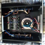
hagustos: that 's Some Huge box.. with a lot of empty space.
Might suggest repositioning the F6 Blu boards one screw mount bay further /closer to the back plate , as far away from the Tx as that big box will allow.
May not help, also won't hurt either
Might suggest repositioning the F6 Blu boards one screw mount bay further /closer to the back plate , as far away from the Tx as that big box will allow.
May not help, also won't hurt either
Hi Everyone,
After two years of waiting in the boxes as parts because of house move and not encouraging circumstances, finally I finished my F6 clone within a week with slow, careful steps.
Boards and Transformers and matched JFets and Keratherm isolators are from diyAudio store, PT is Antek AS4218 all other parts are from Mouser.
But I am hesitant to connect any speaker to it.
After 5 hours of bias and offset adjustment and monitorizing voltages;
Right channel offset is under 10mV with 630mV bias on 0.47Ohm resistor. During 5mV up and down voltage drift offset stays within +- 20mV.
Left channel offset fluctuates rapidly and when set at 630mV bias it is ~ +-40mV but then within 10 minutes voltage drifts + or - 5mV and if +5mV offset becomes ~150mV, if -5mV offset becomes ~ -150mV.
R7, R8 is 5K and Zeners 6.2V.
So,
1- What should I check or replace?
2- Left channel Led did not light up, because it is too much work to change its orientation on an already mounted board, I cut it off but its resistor stayed, any problem with that?
I did it to the right channel also for the sake of symmetry.
Thank you in advance for your suggestions.
Hakan
1) Are you using spring washers on the mosfets?
2) Also retighten the mosfets now that you thermally cycled the amp.
Then retest drift.
Also it would be worthwhile using the LED voltage reference mod if you're not using it, make sure you do the 2 things above first.
The main thing is you don't want it to drift much after it hits thermal equilibrium. The drift at start up is less concerning provided its not a stupid amount.
Last edited:
2 picoDumbs, I was waiting for your suggestions also along other guys.
1-Yes, I have used stainless spring washers, shouldn't I?
2-I will do that too then report about drift.
Hakan
PS; I know it's silly to ask about led resistor, I know it makes no difference electrically if there is a Led connected or not, but for peace of mind I asked and since nobody mentioned it, I am accepting as it makes no harm so I won't bother to cut resistors off.
Seems to be the tap issue as 2 picoDumbs guessed. The bolt holding the Mosfet close to the input loosens. Heatsink will be retapped.
I will report again when it is done.
Regards,
Hakan
I will report again when it is done.
Regards,
Hakan
Today, I remounted the boards on the heatsinks through different taps.
Now Mosfets are firmly attached but left channel offset fluctuation still exists but smaller degree than before.
I decided to do 6L6's suggestion and set bias at 540mV and offset is within limits of ~ +-50mV for a few mV change of bias.
I think it's somewhat safe to hook up a speaker now. I can't wait longer to hear it.
Both Mosfet's Vgs is 4.45V and stable.
Thanks for your help,
Hakan
Hi everybody,
Today I also replaced the 6.2V zener close to offset adj. trimpot and now all is working well.
Bias is 600mV, both channels offsets are under 10mVs.
No hum, no noise.
So the culprit was both faulty zener and loosening bolt.
Thank you all for help.
Also many thanks to Nelson Pass for his generosity.
PS:I have listened music many years happily with a Nelson Pass designed Threshold CAS 1 power amp.
I am in the planning stages of a F6 build and had a few basic questions for the group:
1. Is there a part number available for the binding posts that fit the 4U Deluxe Chassis?
2. I was going to buy the stores PSU PCB. I notice that most builders don't use the rectifier portion of the PCB and opt to use a chassis bolt on bridge rectifier. The bolt on bridge rectifier option seems cheaper, saves precious chassis space all while making good use of the large chassis as a heat sink. Am I missing something?
3. Is there a consensus on how much PSU filtering should be used? I was planning on going with a 400VA transformer. I see build docs listing 40KuF - 72KuF of filtering per channel.
4. I know Nelson Pass mounted his tordial transformer flat against the bottom of the chassis. To save space one could mount perpendicular to the chassis with a L bracket. I notice some have done this. Any downside to this, changing of emanating fields?
5. Is there a BOM with part numbers for the F6 board available?
- Home
- Amplifiers
- Pass Labs
- The diyAudio Firstwatt F6