Hi,ba3 or waynes pre? And yes Ine, they look great, very pretty monster power supply.
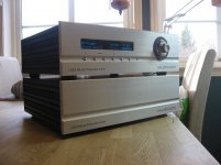
none, this is the UGS Muse pre-amp.
https://www.diyaudio.com/forums/pass-labs/277355-ugs-muse-preamp-gb-39.html#post5463787
Attachments
Last edited:
I use solder based on lead/tin.No lead solder ?
- SAVBIT normal temp.
- Multicore ERSIN362, Sn62%Pb36%Ag2% a LMP (low temp solder)
1) There are nice ones that fit from parts-express, but their new website is unnavigable and I can’t find the link. 🙁
2) You’re not missing anything. The big diodes on the PCB are faster and possibly quieter, but I’ve built many of these with both configurations and they all work well.
3) Get a 300VA with shield, and 15000uf-18000if caps for the board
4) L brackets are nice. Frees up a lot of room.
5) Probably, but it not sure where exactly. BOM go stale very quickly, where the schematic is always right. Order the PCBs so you can see lead spacing and the like and choose the parts you want to use. Or, the store has PCBs with transformers and also transformers + the rest of the parts except Jfets. It’s going to be difficult to order one amp’s worth of parts for cheaper than the bundle’s value.
Here ya go on the Avel-Lindberg transformer @ PartsExpress.
Avel Lindberg Y236651 250VA 18V+18V Toroidal Transformer
Russellc
hi guys,
I'm new to the space, I ordered the F6 boards from DIY but they seem to be out of the stuffing and power supply boards and parts so I have to source everything.
do you know if there is a good alternative board for the power supply that will match with
the f6 I have ordered the Toroidy from pl for the transformer.
any help would be appreciated
thanks
I'm based in. CZ
Currently there are some power supply PCBs designed by Jeff Young in the swap meet:
FS: PCBs (Pass Aleph, SG4, PSUs, Quasimodo, etc.)
They don't have onboard rectifiers so you will use monolithic bridges or separate rectifier boards. These boards have split RC networks based on the schematics on p15 here:
https://firstwatt.com/pdf/art_f6_baf.pdf
FS: PCBs (Pass Aleph, SG4, PSUs, Quasimodo, etc.)
They don't have onboard rectifiers so you will use monolithic bridges or separate rectifier boards. These boards have split RC networks based on the schematics on p15 here:
https://firstwatt.com/pdf/art_f6_baf.pdf
cool thanks,
ill check it out, I have too first decipher all the electronics lingo
I'm still learning 🙂
ill check it out, I have too first decipher all the electronics lingo
I'm still learning 🙂
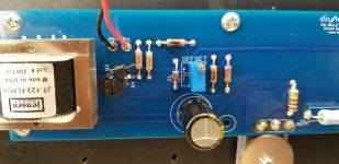
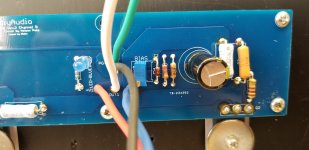
Cooked my R4 18 ohm resistor
Hello,
Need a little help. I tested my PSU with the dim bulb.
PSU shows +25.15/-25.1 with a Antek 32-18
I then tested channel B with dim bulb. Passed.
I was starting to adjust the bias with the dim bulb still in place.
And I fried R4. I used a Dale 18 ohm resistor [RN55D 202IJ 18R2F] from the F6 parts kit.
I had checked and have now rechecked continuity at the Mosfets. All good.
I used the 6.8V Zeners and 3.3K resistors.
I had positioned the pots in the middle of their range.
Nothing else looks fried.
I triple checked Q3 and Q4.
Wires: red to V+, blue to V-, black to ground. White is out and green is out ground.
Led works [yeah].
Any thoughts are appreciated.
Attachments
Hi all,
If I may, some quick questions....
Just about to start my F6 and was thinking....
Shielding the three trafo's?
Shield internal wiring? and if yes chassis ground or circuit ground for shield?
Resistor to dim the LED, any harm to circuit? Value of resistor?
Am thinking a soft start and speaker protection, needed or not?
Riser panels for soft start and speaker protection to create space, make it tidy?
Power input (Schurter) RFI/EMI filter?
Dual power trafo and boards? (Dual mono?)
Any thoughts from experience or tested knowledge would be much appreciated,
I am from the do it once do it to the best of your abilities school of thought, so
With that in mind have I missed anything to make this F6 the best it can be?
Thank you for being here, and thanks in advance for any help👍👍🍻
But most of all thank you N.P. for having us all, broke the mold making you didn't they.....
I don't think its necessary to shield the power wiring DC or AC or the loudspeaker leads
Shield the signal in leads with the screen to circuit ground
Riser panels for soft start and L/S protection, which I think are both essential.
You can try dimming the LED with a larger resistor but it will depend on the LED certainly won't harm the circuit. A general rule of thumb I use 1K per 10volts which puts about 10mA through the LED so for 24V a 2K7 to start with
Keeping the power and signal transformers far apart will help. I finished up fitting both the tx on long thin aluminium strips which I moved, bent, rotated for minimum hum (A bit like the old humbuckers in tape recorders) shielding the txs can be expensive - Mu metal??
I used two transformers, one for the +Ve rail and one for the -Ve rail. about 250VA each
Don't know whether a filtered power inlet is necessary. I have very clean power lines so didn't use one, others will advise accordingly, but it cannot hurt.
John
Hi Onear - See below for a few opinions. Much of this is covered in the build guide thread. I strongly recommend reading it to be sure that you get a few parts values dialed in appropriately for making your bias process as easy as possible. I never like to assume a skill level, but using the exact parts values provided with the kit.... is usually the easiest way to achieve success.
In addition, I recommend checking this out. Yes, it's a modification, but if you grasp it, it might be well worth your time.
Dumb Biasing Mod, applicable to F6 and other Papa Amps. Possibly My Dumbest Idea Yet
How big is the chassis you're using? More space => Better.
1) Static shield wire between primary and secondary of power transformer(s) always nice if you can get it.
2) MuMetal or other around signal transformers. Can't hurt / may help
3) Steel can for power transformers or some other barrier. Can't hurt / may help
4) Proper rotation / orientation / placement of power transformers and associated wiring. Free and always helps me.
tl;dr - no downside to any of it except on your wallet and a bit of complexity. Included with this is... pick a big chassis and orient the signal transformers as far toward the back as possible with the power transformers as close to the front as possible.
Edited to add - I don't think the F6 will pass DC from the pre due to the signal transformer or other design parameters, but an actual expert would need to confirm.
Your call based on your chassis size etc. See also, keeping signal wires short for speaker protection. To steal a phrase... neatness counts.
tl;dr - any time you add more wiring or complexity to make it "better", make sure you have all the fundamental things perfect first.
One (non-expert) opinion.
In addition, I recommend checking this out. Yes, it's a modification, but if you grasp it, it might be well worth your time.
Dumb Biasing Mod, applicable to F6 and other Papa Amps. Possibly My Dumbest Idea Yet
Shielding the three trafo's?
How big is the chassis you're using? More space => Better.
1) Static shield wire between primary and secondary of power transformer(s) always nice if you can get it.
2) MuMetal or other around signal transformers. Can't hurt / may help
3) Steel can for power transformers or some other barrier. Can't hurt / may help
4) Proper rotation / orientation / placement of power transformers and associated wiring. Free and always helps me.
tl;dr - no downside to any of it except on your wallet and a bit of complexity. Included with this is... pick a big chassis and orient the signal transformers as far toward the back as possible with the power transformers as close to the front as possible.
Pick your favorite. See previous answer. Wire routing and proper twisting, keeping wires short etc. will likely yield more benefit. Note, I am separating shield from grounding scheme.Shield internal wiring? and if yes chassis ground or circuit ground for shield?
See previous postResistor to dim the LED, any harm to circuit? Value of resistor?
Matter of opinion. Some type of soft start might be recommended based on your personal choices (transformer VA and PSU caps), but many find that a few thermistors work wonderfully vs. the complexity of a relay-based system etc. Speaker protection - again, a matter of choice. The F6 is stable, but if you have mega-mega buck speakers, and your pre-amp might feed a bit of DC... your call. Belt and suspenders. I don't use speaker protection with any of my amps, and I consider myself very cautious. There is no speaker protection in any commercial First Watt amp to my knowledge. So, what you're worrying about here is based upon your build skill vs. the circuit.Am thinking a soft start and speaker protection, needed or not?
Edited to add - I don't think the F6 will pass DC from the pre due to the signal transformer or other design parameters, but an actual expert would need to confirm.
Riser panels for soft start and speaker protection to create space, make it tidy?
Your call based on your chassis size etc. See also, keeping signal wires short for speaker protection. To steal a phrase... neatness counts.
Why not? They do work. Again, see other areas for higher return on investment, but if you're going all out, have fun.Power input (Schurter) RFI/EMI filter?
See also... why not? Adds a bit of complexity... two big power transformers in the chassis with your signal transformers. If you do it, be good about your chassis size and shielding, or potential benefits might be wasted. Also see, PSU types for ultra low ripple and/or regulation / CLC etc. etc.Dual power trafo and boards? (Dual mono?)
tl;dr - any time you add more wiring or complexity to make it "better", make sure you have all the fundamental things perfect first.
One (non-expert) opinion.
Last edited:
Thank you both for your replies, I will be taking on the advice and following the link.
In answer to the chassis question, Ill be using the DELUXE 4U ALUMINUM, so am trusting there will be enough space for the ideas I'm having.
Quick question, have come across thermistors but am yet to use them.
If the answer is so simple, why have a soft start?
what are the pros and cos of each option?
And how would I calculate the correct value for this amp or others?
Thanks again🙂
The thermistor "is" sort of a soft start. In this application it's used as an in-rush limiter. In-rush limiter and soft start are sometimes used interchangeably... sometimes not. I have not learned why one term is used vs. the other.
I understand the two primary functions to be:
1) Allows you to use a "properly rated" fuse in your circuit that will not blow every time you turn on the amp, but will blow properly if something goes wrong.
2) Longer life of some components
Why use a relay-based type or other method vs. a thermistor? Some people like to take the thermistor out of the equation once the in-rush is over and get back some precious voltage. Possibly some people don't like a really, really hot part in their chassis. Both of those are speculation, but they'd be reasons I'd consider.
What value? - See the schematic for the PSU for the amp you're building. 😀
- Home
- Amplifiers
- Pass Labs
- The diyAudio Firstwatt F6