bullittstang - please provide the ohm reading from R11 to R12 base. Thank you. My boards have the same V.1b number as yours and have been told by the DIY store that no changes have been made to the boards. Need to have someone address the actual problem with the 221 reading on my boards. If it cannot be addressed, then no progress can be made.
Last edited:
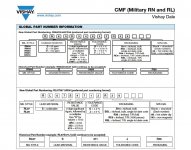
The resistor R11 on the left and right picture has a value of 221000 ohm (2213F = 221 + 3 zeros, F is tolerance)
Last edited:
Basic question, but did you check the resistors prior to installing, just to confirm R?
I would move away from the fixation of point to point R readings. Measure each resistor prior to installation and check again after installation. If memory serves, all the resistors reported correctly via DMM even after they were installed. So no weird parallel resistors that change the resistance on the board.
I would move away from the fixation of point to point R readings. Measure each resistor prior to installation and check again after installation. If memory serves, all the resistors reported correctly via DMM even after they were installed. So no weird parallel resistors that change the resistance on the board.
All resistors checked thoroughly before install. See the description and pictures above for the actual testing methods that do what you request. AGAIN, no progress can be made without finding an explanation for the incorrect reading from R11 to R12 of 221 ohms. This is a fact and you cannot ignore it, move on to other build processes, and create a working board.
Bullittstang: Why won't you provide your reading from R11 to R12? Need this value. Failure to provide on your part muddies the waters.
Bullittstang: Why won't you provide your reading from R11 to R12? Need this value. Failure to provide on your part muddies the waters.
bullittstang - please provide the ohm reading from R11 to R12 base. Thank you. My boards have the same V.1b number as yours and have been told by the DIY store that no changes have been made to the boards. Need to have someone address the actual problem with the 221 reading on my boards. If it cannot be addressed, then no progress can be made.
At my sons soccer game, read my earlier post about resistor readings.
Happy to I measure any point when I get back to the house in a couple hours.
stonegreen writes:
"The resistor R11 on the left picture has a value of 221000 ohm (221 + 3 zeros)"
That is a curiousity of Vishay's device naming. The resistor is a correct 221 ohm one, has been repeatedly checked and its value of 221 appears within certain circuit reads.
I get that everyone wants to find a problem with my description above, what I do not get is why others will not provide their readings from R12 to R11 base. This is not helpful.
Craig,
When a Vishay resistor is labeled 2213 for the component value, that means it is 221k Ohms, aka 221,000 Ohms. Not 221 Ohms, as required. You have installed an incorrect part on your board in at least one location. Saying that you measured them before installing suggests that you are reading your multimeter incorrectly. The Vishay value you need will be labeled 2210.
A lot of people here are trying to help you. You should listen to them.
Last edited:
Folks: Don't pay any more attention to my problems with the boards. Will continue to check out the various short possibilities and report should I find any issues. Thanks as always. Thanks, TA.
First. Post a pic of your actual DMM at the time that it is measuring between those exact two points. Use clip leads if you can't find someone to hold the camera for you.
Please install ALL Dale resistors with their values facing upward.
What do you think your DMM reads when it's measuring 221,100 ohms vs. 221,000 ohms?
Personally, I'd rule that out first. You either have up to seven defective / mis-marked resistors from a very reputable brand... or you've measured incorrectly. I know what I'd rule out first.
Just trying to help, so don't so don't read this if you do not want help.
I experimented with my boards. First checked continuity between the top of R11 and R12. It beeps. Then I installed a 220K resistor for R11 and a 100 for R12. Used my auto-ranging meter and 220 appears on the meter. But there is a little K down in the corner.
so 220K + 100 = 220.K on the meter. Then I repeated the test with a more simple meter. Set to 200 ohms. Shows 1 or over. Same for all the other setting until 2M. Ten it reads 220 with the little K in the corner.
So Craigl59 please verify that you have 221 ohm resistors not 221K ohm resistors. A simple test would be to twist the leads of a 221 and 100 together and then measure the open ends. If 321 does not appear on your meter you have found the problem.
Again I am just trying to help because my next project is the MX2 amp.
Craigl59, if you don't have a component tester I would highly recommend getting one. For example:
https://www.amazon.com/dp/B01MS1FOYM/ref=cm_sw_em_r_mt_dp_ADGG6N2QHGVY94BJF5V8?_encoding=UTF8&psc=1
https://www.amazon.com/dp/B01MS1FOYM/ref=cm_sw_em_r_mt_dp_ADGG6N2QHGVY94BJF5V8?_encoding=UTF8&psc=1
Mmmh.. about 30 amps at R14 and about 1500 watts on the power supply (with LTSpice).Should be popping fuses I would think
Last edited:
Folks: Don't pay any more attention to my problems with the boards. Will continue to check out the various short possibilities and report should I find any issues. Thanks as always. Thanks, TA.
Would have helped if you had measured the board first without installing anything. Take it out of the package, and measure what you see across the two R11 pads. If it measures 0Ohms from factory without any soldering iron ever touching it, then we could assume a board problem (or a broken DMM 😉
The Austin and Mtn View are my two favorite front end boards for the M2x. I liked the Austin so much that I adapted it to use as the front end buffer for my F6. Stay tuned, there is another adaptation on the way..
Well, I think there are great lessons to learn from Craig’s adventure:
- double checking values is never a wasted time
- ensuring letters of values on resistors are facing upwards is not just for “aesthetics” (or ensuring color bands all match the same orientation)
- when requesting measurements it would be ideal to post pictures of the ACTUAL moment of measurement
- it helps to keep the basic rules of series and parallel components at hand. 220k in series with 100R would, indeed just show as, basically, 220K.
With a properly oriented resistor and pictures of the DDM, I believe a lot of time and money could have been saved.
The good part is that, after a long drink sitting down and a couple of breathing exercises, you will get furious at the fact that you are just mad at yourself.
When that happens, please come back and thank all the community that spent so much time helping you troubleshoot!
I have bought the $13 part tester that Mark recommends everywhere, and I put every part that goes into the board first into the tester.
It really is a great investment! Worth the price of a burger!
Rafa.
- Home
- Amplifiers
- Pass Labs
- The diyAudio First Watt M2x