.....also maybe double-check that D1, D2, D3 are installed correct and not "reversed".
All diodes are correct.
Just make R6 about 3k smaller. Do you have a 332K resistor laying around? Parallel that with the 37k and you'll get 33k
I can order the 3332K resistor.
Is another option to use the 20K pot I've ordered? [3296W-1-203RLF] I will receive that before the resistor.
And is my issue the 5K pot I used?
Thanks
Is another option to use the 20K pot I've ordered? [3296W-1-203RLF] I will receive that before the resistor.
And is my issue the 5K pot I used?
Thanks
Kind of yes, but not necessarily. You just need to have fewer ohms in general on that node, since you can't turn it down any further.
Well figured out the problem with the left channel offset. I see now why solder is important. I mounted the MOSFETs but forgot to solder them. Fired the amp up and was able to get the offset to 0.
The first daughter cards I will try are the Norwood boards. I sure hope I soldered that correctly.
The first daughter cards I will try are the Norwood boards. I sure hope I soldered that correctly.
Ok. So I guess I will swap out the pot and see how that goes.
37K resistor plus a 5K pot turned all the way down is 37K.
37K resistor plus a 20K pot turned all the way down is 37K...
Measure the total of pot + resistor and make sure that down is actually down, and if so, you need to make the 37K resistor a little smaller.
BRN - That's great!! Carry on!

.
Well figured out the problem with the left channel offset. I see now why solder is important. I mounted the MOSFETs but forgot to solder them. Fired the amp up and was able to get the offset to 0.
The first daughter cards I will try are the Norwood boards. I sure hope I soldered that correctly.
Doh! 😛 IUf it was the Badger, it might have worked, those damned holes are tight. I usually..... ~censored~
Add an attachment to ground is not so difficult...
Yes Nor6 or Norwood F4 (M2X without transformer
To modify the Norwood IPS is it sufficient to put a resistor divider to ground in the feedback loop? DC coupled?
@6L6
Would you mind to share your ideas about required modifications to use a norwood IPS as frontend with F6 output stage? Sounds like a wonderfull combination.
Layout a new PCB with a feedback loop. Add a PSU section, volume pot, select, and it's a preamp. 🙂
Last edited:
Layout a new PCB with a feedback loop. Add a PSU section, volume pot, select, and it's a preamp.
You know, ...
the video IS PROBABLY RIGHT
Layout a new PCB with a feedback loop. Add a PSU section, volume pot, select, and it's a preamp. 🙂
Thought you had something different in mind with post #4198 The diyAudio First Watt M2x.
Sorry for my misinterpreting.
@6L6
Would you mind to share your ideas about required modifications to use a norwood IPS as frontend with F6 output stage? Sounds like a wonderfull combination.
You should definitely check Adcom’s GFP-565 Preamplifier and/or the modifications suggested by Gary Galo in this article:
Adcom’s GFP 565 Preamp Mods, Part 3 - Walt ??s GFP 565 Preamp Mods, Part 3 40 audioXpress 1/04 -
especially:
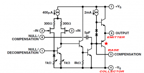
"The AD744 has a unique feature: the output can be taken from compensation pin 5, bypassing the Class–AB output stage.
This is how the chip was used in the DAC960 project. Walt (Jung) informed me that pin 5 is capable of driving the high–impedance local feedback network in the new topology."
Last edited:
1543 -
Norwood, if you think of it as a gain block using AD744 + HA5002, can be configured as a buffer (as we have in the M2x project) or with gain. (because it’s a composite opamp circuit)
You cannot configure it for gain using the M2x daughter card PCB. These cards are buffers, only.
Any use of the Norwood circuit for gain will need a new PCB. Could it be used in conjunction with the F6? Yes. Take the F6 circuit and remove the input buffer, have the “gain Norwood“ circuit drive the transformer, and you’ve have a very nice amp!
Could Norwood be used as the gain section of a linestage? Yes. Layout a new PCB with the Norwood circuit, add whatever preamp features you’d like, and the result would be a linestage of excellence. (I’m actually very interested in this particular idea and one of these days will peruse it... 🙂 )
The AD744 has a unique feature: the output can be taken from compensation pin 5, bypassing the Class–AB output stage.
This is how the chip was used in the DAC960 project. Walt (Jung) informed me that pin 5 is capable of driving the high–impedance local feedback network in the new topology."
The person who designed the AD744 is still alive, and in fact is a member of this diyAudio website. When I discussed AD744+Norwood with him back in Jan 2018 [compare with the date of post #1 in this thread!], he nudged me to carefully look at the internal schematic of the chip, paying particular attention to the PNP transistor which drives the output pin.
It seems that a few nosebleed-performance ADI customers bought the AD744 and then connected a high performance (fT = 750 MHz, see datasheet Figure 8) discrete PNP in parallel with the internal PNP, using those pins. This gave vast improvement in opamp performance. However the particular discrete PNP they used, the PN4258, is no longer in mass production; today, non-counterfeit parts are difficult to find.
_
Attachments
Last edited:
For those who are thinking about laying out their own PCB using AD744 + HA9P5002 chips, I offer a mild suggestion:
Strongly consider creating your own PCB "footprints" for SMD components, and not using the ones which come with Eagle / KiCad / ExpressPCB / etc. Your goal is different than the goal of a commercial electronics business. You want to make a PCB which is beginner-friendly and easy to solder, at home, by DIYers with inexpensive equipment. You're not trying to get maximum packing density, or ease-of-placement-by-robots, or any of the other important metrics in a high volume, high yield factory.
Think hard about what makes it easy or difficult to place and hand-solder an SOIC-8 or an SOT-23 or a 1206 component. Then design your "footprints" to remove some of the difficulty. What gave you trouble on the last few SMD boards you built by hand? How could you make that easier with different footprints?
Think hard about what makes it easy or difficult to probe an SMD board, either with a DVM set on continuity buzzer mode (looking for opens and shorts), or with an oscilloscope probe. Then design your "footprints" to remove some of the difficulty. When you probed the last couple of SMD boards you built, what gave you trouble? How could you make that easier with different footprints?
The M2x Norwood board has a grand total of seven different PCB "footprints" and one of them is the mounting hole for the M3 bolt. So we're not talking about creating a giant number of new footprints, nor a huge number of additional man-hours.
Looks pretty similar to 2N4258. Product info page Parts | 2N4258 | New Jersey Semiconductor still shows >6000 in stock. Most likely original part. Wiltronics also have TO39 metal package version 2N4258 - Bipolar Transistors TO-39 | Wiltronics for our friends downunder.
Attachments
Last edited:
It seems that a few nosebleed-performance ADI customers bought the AD744 and then connected a high performance (fT = 750 MHz, see datasheet Figure 8) discrete PNP in parallel with the internal PNP, using those pins. This gave vast improvement in opamp performance.
_
Very clever, thanks for the info.
Anyway, use pin 5 as an output and bypassing the Class–AB output stage AD744 also seems to be an interesting option.
Funny there is discussion about SMD soldering. I just got my M2x running, but one of my Norwood boards is not working. I have never been good a soldering SMDs. I'm going to take a close look at the board and see if there is anything obvious that could be the problem. Most likely I will just apply some the iron the connections and see if that fixes it.
In the meantime I'm running the amp with the Mountain View daughter boards. It sounds very good, even without break in. Can't wait to try the other boards.
In the meantime I'm running the amp with the Mountain View daughter boards. It sounds very good, even without break in. Can't wait to try the other boards.
6L6,
Thanks a lot for your explanation.
According to F6 manual the line level transformer isolates the drive signal to the output stage and acts as the feedback element for the amplifier.
Mosfets are working in “Common Source” mode and this single stage provides both the voltage and current gain.
The input Jfet are only followers to buffer the transformer for high input impedance.
Excuse me if this is a dumb question:
I am right that the Norwood cant work as buffer / follower only and must be a Gain-Norwood when used in F6 circuit because the feedback from transformer would cause stability problems?
1543 -
Norwood, if you think of it as a gain block using AD744 + HA5002, can be configured as a buffer (as we have in the M2x project) or with gain. (because it’s a composite opamp circuit)
You cannot configure it for gain using the M2x daughter card PCB. These cards are buffers, only.
Any use of the Norwood circuit for gain will need a new PCB. Could it be used in conjunction with the F6? Yes. Take the F6 circuit and remove the input buffer, have the “gain Norwood“ circuit drive the transformer, and you’ve have a very nice amp!
Could Norwood be used as the gain section of a linestage? Yes. Layout a new PCB with the Norwood circuit, add whatever preamp features you’d like, and the result would be a linestage of excellence. (I’m actually very interested in this particular idea and one of these days will peruse it... 🙂 )
- Home
- Amplifiers
- Pass Labs
- The diyAudio First Watt M2x