Please, more exact information about the Meanwell.
Was this meant for me?
Quick question re the blade connectors. Is just soldering them in place enough to ensure a robust connection to the board? I ask because of a recent experience with a commercial(ish) product that resulted in a few of the blades pulling off of the board when I disconnected the power supply wiring to make some changes.
I can tell you that mine are extremely secure. To be fair, I may have used a bit of "extra" solder. The connections are quite tight and require a bit of wiggling and tugging to get them loose. Never once did I think the blades would come loose from the board. In fact, one of my plastic covers slipped off of the female connection. All are still very secure, and I've swapped the connectors on and off at least 10X for various reasons. Hope that helps.
If you solder so solder just gets through on the other side then blades are very secure. I used silvered Amphenol type.....seems to be good stuff. For the Female that goes on the blades it is important to also get good "ISO stuff"…..especially if you crimp as I do.
I've actually used a very small (3/16" wide blade) slotted screwdriver blade to loosen some of the very tightest female blade connectors. Just a teeny little bit, so the PCBoard doesn't flex quite as much when pushing the female down onto the male. Only about half of the females were super tight enough that I wanted to loosen them a little bit. They're still plenty grippy even after loosening.
Thanks guys. I used a touch of epoxy to repair the other board's connectors (and to reinforce another of the same type of board that I have) but if I'm starting from scratch on these it sounds like these will be fine. Great boards, by the way!
Quick question re the blade connectors. Is just soldering them in place enough to ensure a robust connection to the board? I ask because of a recent experience with a commercial(ish) product that resulted in a few of the blades pulling off of the board when I disconnected the power supply wiring to make some changes.
I gave the tabs a bit of a squeeze with pliers. Not enough to compress the through hole, but just enough to pull them tight (ish) against the board before soldering.
It just makes them easier to solder that way.
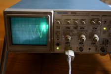
I have started testing my M2X mono blocks. If looks ok so far.....I think. I use 8 ohm resistor as load. Sinus generator as input signal. I have added 3 scope pictures. Settings is 10V/Div. Frequency set to 20 Hz looks fine but if reduced to 10 Hz signal looks like cross-over distortion? ….is that because amp runs out of bias? If I reduce input signal a bit signal looks ok again as seen in last picture. Rails are +-23V and bias approx. 1.3 A.
Attachments


try 2Hz - it'll look even funnier

so , Iron on input , bias spreader with still finite capacity across , and 30Vpp output .........
that looks as damn fine 10Hz , if you ask me
so , Iron on input , bias spreader with still finite capacity across , and 30Vpp output .........
that looks as damn fine 10Hz , if you ask me
Easiest way to find out is to attach probe to cathode of D1 and/or anode of D3. If the goofy behavior is present on the output but NOT present on the gates of the output transistors, that is significant. On the other hand if the goofy behavior is present on BOTH, that is also significant.
It looks "goofy" at anode of D3.....so distortion from Edcor?
Then I have to measure before Edcor I guess to find out...…...
Then I have to measure before Edcor I guess to find out...…...
Input to Tucson (output of generator) looks fine but already output of Tucson starts to look "goofy" at 10 Hz.....but not as "goofy" as Edcor output. So Tucson has a problem with low frequencies? ….it is with OPA604.
Swap in another of your daughter cards to find out. I happen to know that you have you two working Norwood boards, because I built them myself and shipped them to you on 07 Jan 2019. Put them in and see how well or how poorly they work, when the M2x output looks like photo #2 of post 2250.
Maybe you will conclude that you can accept or tolerate an M2x amplifier whose maximum undistorted output power begins to fall when producing output sinewaves at frequencies below 20 Hertz.
~
Maybe you will conclude that you can accept or tolerate an M2x amplifier whose maximum undistorted output power begins to fall when producing output sinewaves at frequencies below 20 Hertz.
~
Last edited:
Yes I have the red Norwoods. I will test other M2X amp also with Tucson. Then I can try to swap to Norwoods and see if they can go lower in frequency. Edcor is probably a difficult load at low frequencies? …..I wonder how original M2 JFET input handles Edcor.
The purpose of the test is to discover whether the Edcor transformer is working well and the daughter card is misbehaving, or whether the Edcor transformer is misbehaving and the daughter card is working well.
Or perhaps the data in post 2254 tells us the answer immediately. Input to Edcor is slightly bad, output from Edcor is very bad. What does this mean, Dr. Watson?
Or perhaps the data in post 2254 tells us the answer immediately. Input to Edcor is slightly bad, output from Edcor is very bad. What does this mean, Dr. Watson?
"Edcor transformer is behaving nominally ?"
(distortion / saturation of transformer at its low-frequency bandwidth limit ... 😛)
(distortion / saturation of transformer at its low-frequency bandwidth limit ... 😛)
Edcor may be the largest contributor to the distortion. …..but will be interesting to see with other input boards that has more driving power so there is a clean input signal to Edcor. I also need to check that input boards has good connection. We see when 2nd board is tested on other amp.
- Home
- Amplifiers
- Pass Labs
- The diyAudio First Watt M2x