M2 can't be simpler , if done methodically
why including State Surveillance System in , I can't fathom ..... especially if darn thing can't be made operational in simplest form?
as Jim said - less words , pictures and exact schematics are good start; then making amp itself operational , then play with delusional addendums

why including State Surveillance System in , I can't fathom ..... especially if darn thing can't be made operational in simplest form?
as Jim said - less words , pictures and exact schematics are good start; then making amp itself operational , then play with delusional addendums
Thanks for the replies.
I thought I had been clear about what the problem is.
In short,
I replaced the power supply.
In a moment of stupidity I swapped the polarity at the amp board.
The daughter board gets too hot to touch very rapidly.
The voltage measured at pins 1 to 3 of the daughter board starts at ~50V and then falls to about 30V.
As for the rest,
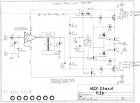
I posted the exact schematic of the power supply, as well as the M2x schematic, a block diagram, and a table with test results.
I also described what I have done so far.
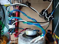
Below is a pic of the deconstructed "power supply," it is now nothing more than a transformer, rectifier, and 2 smoothing caps. I flagged the 0V line with blue tape for clarity.
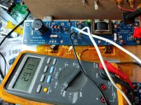
Also is a pic of the amp board. Not sure why it is needed, this was a working amp, so I included the meter showing the voltage reading.
Thanks again.
-Josh
I thought I had been clear about what the problem is.
In short,
I replaced the power supply.
In a moment of stupidity I swapped the polarity at the amp board.
The daughter board gets too hot to touch very rapidly.
The voltage measured at pins 1 to 3 of the daughter board starts at ~50V and then falls to about 30V.
As for the rest,
I posted the exact schematic of the power supply, as well as the M2x schematic, a block diagram, and a table with test results.
I also described what I have done so far.
Below is a pic of the deconstructed "power supply," it is now nothing more than a transformer, rectifier, and 2 smoothing caps. I flagged the 0V line with blue tape for clarity.
Also is a pic of the amp board. Not sure why it is needed, this was a working amp, so I included the meter showing the voltage reading.
Thanks again.
-Josh
Attachments
Shouldn't there be 2 resistors to the right of the EDCOR just behind the pot? I only see one soldier or is it because of the photo angle?
@dewdrop
The meter should read 50V not 25V. The amp runs from -25V to 25V for a total of 50V potential. The two posts that go into the input stage are tied directly to V- and V+.
If R13 and R14 are removed (this opens the connection between the MOSFET sources), the voltage will read 50V steady.
@elwood625 you are referring to R6 and R8 I think. R8 is clearly visible, R6 is hiding next to the Edcor.
The only part not installed is CB3, and it will operate with out it.
So is the amplifier power section working properly with no daughter card attached? No offset, proper bias?
So is the amplifier power section working properly with no daughter card attached? No offset, proper bias?
DC offset is close to 0. Bias is handled by the autoformer, I do not know how to even check it properly on this amp.
The amp is not working properly, something is loading it down to ~30 volts.
If i install a daughter card, it over heats almost immediately.
I have been using Norwood. After your question, I installed Tuscon just in case Norwood is toasted. The behavior is the same, it starts at 50V, and falls off. I shut it down before it reached 49V so I would not cook the card.
To the best of my knowledge, the amp should "work" with no daughter card, and you should even be able to adjust the offset. But with no daughter card, there is nothing for the amp circuit to follow, so it will just sit and idle.
for OS , only two things are important - DC offset and Iq
DC offset measured normally between output hot and GND
Iq measured as voltage across one of mosfet source resistors - say 1A6 across 0R47 will give 0V752
so anything between 550mV and 800mV is in ballpark , slightly dependable of optocoupler class etc.
input autoformer is having nothing with biasing , it's there for AC voltage gain
for OS , only two things are important - DC offset and Iq
DC offset measured normally between output hot and GND
Iq measured as voltage across one of mosfet source resistors - say 1A6 across 0R47 will give 0V752
so anything between 550mV and 800mV is in ballpark , slightly dependable of optocoupler class etc.
input autoformer is having nothing with biasing , it's there for AC voltage gain
I feel like there is a large mis-understanding of my problem here.
I do really appreciate you taking the time to reply.
Here is a schematic where I labeled the voltage drop across all the resistors.
In specific reply to your comment, the voltage drop over the source resistors is 0V at start up when the rail voltage is 50V, and climbs to 0.572V after the rail to rail voltage has dropped to 29.3 volts. So about 1.22A
I also included the voltage measured at each MOSFET with the probe on GND.P
Thank you,
-Josh
Attachments
optocoupler is taking care of Iq of OS, and 570mV across 0R47 is good value, even if little low
if you have "regular" 2x18Vac or 36Vac-CT (center-tapped) xformer , under load you can expect something as 22Vdc rails , so 44Vdc rail to rail
with said Iq , it seems OS is in order , but you have problems with PSU , if having just 29.3Vdc rail to ral
and - do make distinction when writing - between rail vs. rail-to-rail voltage, to avoid misunderstandings ......
post pictures
So these voltages are from your PCB with the +/-15v PSU and absolutely nothing else attached to or touching the amp board?
Put a signal on daughter card pin4 and ground. Use your phone or something. Does the amp play?
And please, more photos.
Put a signal on daughter card pin4 and ground. Use your phone or something. Does the amp play?
And please, more photos.
.......
if you have "regular" 2x18Vac or 36Vac-CT (center-tapped) xformer , under load you can expect something as 22Vdc rails , so 44Vdc rail to rail...........
Yes, there is nothing touching the amp board. The MOSFETS are screwed to the heat sink. I did replace the Silpads.So these voltages are from your PCB with the +/-15v PSU and absolutely nothing else attached to or touching the amp board?
Put a signal on daughter card pin4 and ground. Use your phone or something. Does the amp play?
And please, more photos.
The was able to hook up my phone to the input, and the amp did play.
@Zen Mod
My transformer is an Antek 400VA 2x18VAC. Pretty much the standard item here.
I really appreciate you all taking the time to help me out, and hold my hand.
What next?
The Norwood board gets too hot to touch almost right away. I am hesitant to put another daughter board on, though I would be willing to try Tuscon with the DIN8 opamp. It is the cheapest and easiest to repopulate if it smokes.
Thanks,
-Josh
You need to find out why your PSU drops from 44V R2R to 29V R2R first before you try anything else. It is an error that it drops that much. Either your have very high impedance somewhere so you have a large voltage drop there or your pull too much current from the PSU so it drops. I would start testing PSU without any boards connected and use a large power resistors (heatsinked) to load the PSU. Then I would measure the 2 X 18 VAC, measure after diodes bridges to measure 2 x 23 VDC to first set of caps etc. An oscilloscope would be very useful to measure ripple.
Ok, so assuming the amplifier power section is fine after the last test, it seems that your Norwoods are bad. Do you have another buffer to try?
And would still like photos. 😀
And would still like photos. 😀
Yes photos. When I installed my Norwood boards the lock washers came dangerously close to a resistor...point is, the only way someone here might catch something like that is with clear photos.
The reason why the input boards got very hot is probably that they got reverse voltage. Opamps don't like that. Even that they get correct voltage afterwards they may still get very hot because opamps are damaged and high currents gets through them. When PSU is tested and OK it should be safe to try with a new input board. But first ensure that PSU is 100% OK.
@MEPER
I agree, having all those tools would be the best and most wonderful thing.
I have done my best to get around my lack of test equipment with part substitutions.
The current rectifiers are known good, I swapped in a brand new transformer, and eliminated the circuit board from the power supply. The only parts that are untested are the 2 caps shown in the pic above.
The good news that I have solved the voltage issue.
It occurred to me that blowing the fuses might have damaged the filtered power inlet, so I swapped it out with an unfiltered unit and it.
The unit in question is this one in case folks want a part to avoid.
FN9260B-10-06 Schaffner | Mouser
The voltage now stabilizes at 48.6V rail-to-rail.
I hooked up channel B to my phone with no daughter card it it also worked.
The bad news is the Norwood card. I have been working on channel A up to this point and had not noticed that the card on channel B actually got hot enough to melt the solder.
See pic.
Are there any other images people would like to see? I am not trying to hide things, just not sure what to take a pic of (unless you want a pic of my bench covered in piles of junk...).
Like I said earlier, the amp is just lashed up on some MDF. I have a 5U case it will go in once I verify everything is working.
@KevinHeem
I was critical of the lock washers recommended, and they manner in which they are used in this thread a while ago (and got teased for it 🙂). The washers and usage are wrong in about every way they could be wrong.
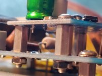
In the attached pic of the cooked Norwood board, I removed one of the screws to show the lock washer.
This board has been swapped no less than 2 dozen times, and the gold plating on the holes is still in perfect condition.
The other pic is a close up of the daughter board stand off. No washer between the stand off and the circuit board. Washers are only between the fasteners and the boards. The washer have the cuts to the inside so they do not damage the foil. The cap head screws are stainless. I selected the stand offs for having round seats (not hex) and for having large surface area. They are also plated with something that is "supposed" to remain conductive, dunno, but they are used in telecom.
I can swap in another daughter board if that is what seems to be the next step.
Once again, thank you all for you time and attention.
-Josh
P.S. does anyone have a link for a good inline filter? I wanted to have the filter separate from the IEC power inlet, and this seems like the time to implement that.
I agree, having all those tools would be the best and most wonderful thing.
I have done my best to get around my lack of test equipment with part substitutions.
The current rectifiers are known good, I swapped in a brand new transformer, and eliminated the circuit board from the power supply. The only parts that are untested are the 2 caps shown in the pic above.
The good news that I have solved the voltage issue.
It occurred to me that blowing the fuses might have damaged the filtered power inlet, so I swapped it out with an unfiltered unit and it.
The unit in question is this one in case folks want a part to avoid.
FN9260B-10-06 Schaffner | Mouser
The voltage now stabilizes at 48.6V rail-to-rail.
I hooked up channel B to my phone with no daughter card it it also worked.
The bad news is the Norwood card. I have been working on channel A up to this point and had not noticed that the card on channel B actually got hot enough to melt the solder.
See pic.
Are there any other images people would like to see? I am not trying to hide things, just not sure what to take a pic of (unless you want a pic of my bench covered in piles of junk...).
Like I said earlier, the amp is just lashed up on some MDF. I have a 5U case it will go in once I verify everything is working.
@KevinHeem
I was critical of the lock washers recommended, and they manner in which they are used in this thread a while ago (and got teased for it 🙂). The washers and usage are wrong in about every way they could be wrong.
In the attached pic of the cooked Norwood board, I removed one of the screws to show the lock washer.
This board has been swapped no less than 2 dozen times, and the gold plating on the holes is still in perfect condition.
The other pic is a close up of the daughter board stand off. No washer between the stand off and the circuit board. Washers are only between the fasteners and the boards. The washer have the cuts to the inside so they do not damage the foil. The cap head screws are stainless. I selected the stand offs for having round seats (not hex) and for having large surface area. They are also plated with something that is "supposed" to remain conductive, dunno, but they are used in telecom.
I can swap in another daughter board if that is what seems to be the next step.
Once again, thank you all for you time and attention.
-Josh
P.S. does anyone have a link for a good inline filter? I wanted to have the filter separate from the IEC power inlet, and this seems like the time to implement that.
Attachments

The CORCOM "2VR1" inline filter is rated for 2A at 120VAC/250VAC, which ought to be more than enough for any of the First Watt class-A amplifiers.
Its datasheet is here . You'll notice that the 2VR1 is a two stage filter while many others are single stage filters; after all, the first rule of DIY is,
And, with that in mind, nobody here can stop you from connecting N=4 of the 2VR1 filters in series, between the mains and the primary of the power transformer.
Both DigiKey and Mouser are authorized distributors and both have many dozens in stock, on the shelf.
Its datasheet is here . You'll notice that the 2VR1 is a two stage filter while many others are single stage filters; after all, the first rule of DIY is,
- If some is good then more is better
Both DigiKey and Mouser are authorized distributors and both have many dozens in stock, on the shelf.
Last edited:
Joahua43214,
Reverse polarity probably killed the electrolytics and the opamps on your Norwood. Once an electrolytic cap gets reveresed, there is permanent damage to the insulator layer inside - it must be replaced. But sounds like your opamps on the Norwood are fired. Should not be hot. Try a brand new buffer card - made with all new parts. The Tucson is probably the easiset to build and least number of parts. The Austin is probably most number of components but all discretes and is very robust. It could probably survide being reversed power for a few seconds, electrolytics not witshtanding. The good news is that it sounds like your main amp board and PSU are now fine as confirmed by bypassing the input buffer. Good luck!
Btw, you are probably worrying too much about a filtered IEC inlet. Get a new one if you are - Schurter's are really nice and have published graphs of their filters. Here is an inline filter separate from IEC socket.
5500.2102 Schurter Inc. | Filters | DigiKey
First order of business is getting the amp to work before worrying about EMI/RFI noise on your mains.
Last edited:
- Home
- Amplifiers
- Pass Labs
- The diyAudio First Watt M2x