….I wonder who made the shielding case for the Edcor…..
Me, with my own two hands.....
Me, with my own two hands.....
Ok....you made a small template to cut the mu-metal from?
Can you remember how much it dampened the 60/120 Hz noise?
The input circuit with the jfets you used fixed resistor values. Did you do any fine tuning to get zero DC offset and/or fine tuning to a specific distortion profile (like we do in BA3-pre using P3)? …..your input circuit was DC coupled to Edcor?
Something I wondered when looking at the amp boards from 6moons review. There is a single resistor at the far end from input. Why is he sitting so alone and isolated from the others?
Nice copper shield and build!
Copper shield is more to shield against RF than magnetic induced noise?
It could be interesting to "just" change copper shield to mu-metal shield and then make the same measurements to see if it would lower the 60/120 Hz noise.
https://www.diyaudio.com/forums/pass-labs/321925-diyaudio-watt-m2x-143.html#post5701193
The diyAudio First Watt M2x
The diyAudio First Watt M2x
Ok.....I use a 500VA Toroid for each mono block. This ensure that flux will stay inside the core as toriods are hugely over dimensioned. Then it has a two layer special steel band around it to shield it (from DonAudio). Then toroid is placed a far as possible from Edcor in the chassis. So......so far so good. I look forward to see the results. Edcor has both copper tape and mu-metal around it. If this is not enough a mu-metal case can be made to put around it also. I like the mu-metal band around it as this also protects the backside of Edcor. A case only protects the top.
In my design I ensured to have short wires from transformer outputs to diodes as these wires radiates a lot of noise as there are large peak currents to charge the capacitors through the diodes. Maybe the choice of schottky diodes helps a little here?
I hope "my thinkings" will benefit at the end.....we will see…..
I hope "my thinkings" will benefit at the end.....we will see…..
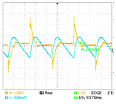
There is a picture here that shows how current looks like in a full rectifier circuit. Yellow is the current. These current peaks looks "nasty" as they rise very fast so they can couple capacitive with other circuits that are close to the wires that are connected to the rectifier. Wrapped around the Edcor would not be good 🙂
I wonder how high frequency these wires can radiate. If there are also RF noise from these wires caused by the fast rise of current?
I wonder how high frequency these wires can radiate. If there are also RF noise from these wires caused by the fast rise of current?
Attachments
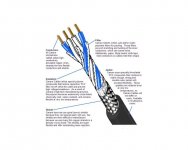
I have long defended, unsuccessfully, the use of star quad cables also in the internal wiring. Especially for Class D amplification and preamps, phono, dac .... but people prefer the twisted of all life. Also aluminum boxes with thin walls is usual but not for the best.
Star quad cable…….had to look that up. Used a lot as microphone cable it seems. That would require some preparation to use it as PSU wiring. Screened wires always takes a bit longer......would also require large dimension and it will be thick…...it will not be this time 🙂
Attachments
I spent yesterday chasing 60 & 120 hz noise, no luck. So, today I installed Ishikawa, here is the initial distortion analysis with RV1 at dead center.
Once again, the amp was allowed 1 hour to warm up, measurement at 1 watt @ 4 ohm load.
Once again, the amp was allowed 1 hour to warm up, measurement at 1 watt @ 4 ohm load.
Attachments
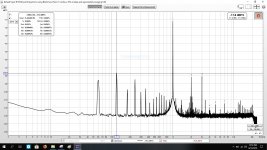
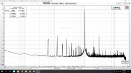
I adjusted RV1 for equal levels for 2nd and 3rd harmonic, within 0.001 - 0.002% difference. About 1 1/2 full turns CCW adjustment of RV1.
In regards to the 60 & 120 hz noise, I performed the following with NO heard or measured difference.
1 - Removed ground wire from EDCOR shield to ground, NC.
2 - Removed the ground from the Toroid shield and case, NC.
3 - Removed the EDCOR shield, NC.
4 - Moved the speaker ground point from the amp pc board to the power supply pc board, NC.
5 - Removed Zen Mod mod of run caps, NC (except the sound stage shrank as far as depth). I used piggyback spade terminals so I could swap them in and out.
What measures good, in this case, does not sound better.
Today I'm going to swap rectifier bridges, glad I used spade terminals instead of soldering.
By the way, 6L6 & Mark Johnson, hurray for using spade terminals on the amp pc board and simple 3mm nuts and washers for the IPS boards. After swapping the IPS boards three times, the star washers need to be replaced, they flatten out.
Attachments

Then it must be "Edcor pickup"......probably only solution is mu-metal shield?
If you ground output of Edcor (with shorted RCA input) …..then noise must disappear. It should be safe to do it at the "Edcor side" of C2?
Just to verify that it is not something else…….
If you ground output of Edcor (with shorted RCA input) …..then noise must disappear. It should be safe to do it at the "Edcor side" of C2?
Just to verify that it is not something else…….
The odd thing is, when the CD player is paused, and I rotate the volume control on the preamp to full volume, the speakers are dead quiet, no hum, hiss, etc.
I'm going to spend the next few days enjoying the music with Ishikawa, already my favorite.
Joe Jackson NIGHT AND DAY, playing now. Next Crowded House, nothing like the Finn brothers.
I'm going to spend the next few days enjoying the music with Ishikawa, already my favorite.
Joe Jackson NIGHT AND DAY, playing now. Next Crowded House, nothing like the Finn brothers.
Dead quiet even with ear to tweeter?
The 120 Hz noise is 65 dB down or so......it may look worse than it really is.
Enjoy music 🙂
The 120 Hz noise is 65 dB down or so......it may look worse than it really is.
Enjoy music 🙂
I rotate the volume control on the preamp to full volume, the speakers are dead quiet, no hum, hiss, etc.
🙂 🙂 🙂
😀 😀 😀

Perfect! You are done, no need to worry, enjoy the amplifier!!
Thanks 6L6!
Voodoo Weekends' new double album and this amp are a great combination. Had the whole family listening, the music drew them in one at a time.
Perfect
Voodoo Weekends' new double album and this amp are a great combination. Had the whole family listening, the music drew them in one at a time.
Perfect
I wonder how high frequency these wires can radiate. If there are also RF noise from these wires caused by the fast rise of current?
We try to at least have twisted pairs of wires to keep radiated noise
down. That said, if your transformer is in the same chassis it will be the
elephant on the dance floor. Shielding is good, and often the noise
can be minimized by rotating the transformer.
- Home
- Amplifiers
- Pass Labs
- The diyAudio First Watt M2x