Oops. xrk971 - I should know better since you helped me with these measurements, it should read, DMM measured output of 2 vac.
An easy way to find out is to plug in another input stage daughter card and see whether anything changes. Tucson-SMD with the OPA-1611 would be a good choice.
Most of these input stage boards are much lower THD than 0.03%, and so what you see is the secret sauce, or the “DNA” of the M2 - the harmonic distortion profile is dominated by the Edcor. Take that out and it won’t sound the same, it will sound like a big Whammy.
Perhaps that means M2x "should" sound the same, no matter which input stage daughter card is installed.
Well there are some differences due to slight phase differences imparted by the topology of the circuit. They are very subtle - and mostly impact stereo imaging and soundstage.
The circuits do indeed have different topologies. That is what makes them different. If they sound different OF COURSE the differences in circuit topology are the reason. They all operate in the same environment (supply voltage, temperature, airflow, input signal, output load) so that's not the reason for sonic differences. Okay, if that's not it, then what's left? The circuit topologies are different, indisputably. An obvious fact that anyone who looks at the schematics can instantly see. Drawing a red circle around the obvious is not an act of trailblazing insight.
_
_
Last edited:
Thanks for sharing elwood65 and look forward to more measurements with some of the other input stage boards installed!
From the FIRSTWATT website, THD for the M2 is listed as 0.050%, noise is 500uV with gain at 15dB.
My M2X ripple measured from each diode bridge = 0.150 vac
Ripple measured at each rail = 0.050 vac (50 mV).
Since I built an F5 power supply, I checked in the F5 article and found ripple as 0.070 vac (70 mV).
Distortion analysis for Tucson IPS, 1 watt @ 4 ohms.
Saturday = Austin
Sunday = Ishikawa
My M2X ripple measured from each diode bridge = 0.150 vac
Ripple measured at each rail = 0.050 vac (50 mV).
Since I built an F5 power supply, I checked in the F5 article and found ripple as 0.070 vac (70 mV).
Distortion analysis for Tucson IPS, 1 watt @ 4 ohms.
Saturday = Austin
Sunday = Ishikawa
Attachments
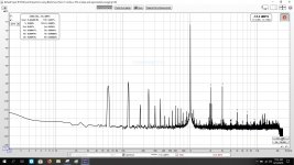
......but can you hear "buzz" in the speakers?
I would like to have some "clean up" at the left side of the fundamental. It is all 60 and 120 Hz and harmonics of these. Do you think it is "Edcor pickup" or caused by ripple? ….or maybe both?
I would like to have some "clean up" at the left side of the fundamental. It is all 60 and 120 Hz and harmonics of these. Do you think it is "Edcor pickup" or caused by ripple? ….or maybe both?
elwood625,
Thanks for getting the Tuscon measurement done.
Are you also doing subjective listening tests with each change of input stage daughter card?
Thanks for getting the Tuscon measurement done.
Are you also doing subjective listening tests with each change of input stage daughter card?
When I switched to the SLB cap multiplier PSU, the hum/buzz on my M2X completely went away. It has ripple under 1mV rms. But mu metal shielding on Edcor is also important. Noise measures 100uV to 200uV rms at amp output with Fluke 101 on mV ac.
I have shielded Edcor with both copper tape and mu-metal foil and I am building the PSU's for M2X in the moment. The goal is to have very little 50/100 Hz at the amp output. Will see how all my efforts turns out. Need to make a power amp to Focusrite interface so I can measure the distortion. First try will be with Tucson input boards with OPA604 opamp. Seems to be an old classic FET input opamp.
It is interesting to have a look inside the original FW M2:
6moons audio reviews: FirstWatt M2
….I wonder who made the shielding case for the Edcor…..
6moons audio reviews: FirstWatt M2
….I wonder who made the shielding case for the Edcor…..
I have shielded Edcor with both copper tape and mu-metal foil and I am building the PSU's for M2X in the moment. The goal is to have very little 50/100 Hz at the amp output. Will see how all my efforts turns out. Need to make a power amp to Focusrite interface so I can measure the distortion. First try will be with Tucson input boards with OPA604 opamp. Seems to be an old classic FET input opamp.
Were you going to try the SLB power supply? It is the best Class A PSU I have ever used - it stops mains hum in its tracks. It has a bunch of extra ground spade terminals on the main star hub ground plane. Makes going to true star topology for grounding very easy. Also has built in NTC and bypass cap for connection to chassis/earth ground.
No....my approach is more "classic". I build mono blocks. The toroid has a magnetic shield and as I use 5U Deluxe x2 I have a lot of space inside so toroid can be placed far away from Edcor. I use DiyAudio store PSU board as basis using Cree Schottky diodes. Then I have extra LC stages using 2.5 mH / 10A DC filter chokes together with Jensen 4-pole caps as the last filtering. The simulation also say around 1 mV ripple at 2A current. Will post some pictures when I am almost there…..
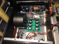
Nice copper shield and build!
Copper shield is more to shield against RF than magnetic induced noise?
It could be interesting to "just" change copper shield to mu-metal shield and then make the same measurements to see if it would lower the 60/120 Hz noise.
Copper shield is more to shield against RF than magnetic induced noise?
It could be interesting to "just" change copper shield to mu-metal shield and then make the same measurements to see if it would lower the 60/120 Hz noise.
zman01 - Yes, I am listening to each IPS, however it's in the shop area not the primary listening room. I have Boston Acoustics bookshelf speakers in the shop.
My main intent with these measurements is to be able to adjust RV1 on the Ishikawa board. If Austin IPS has the same even 2nd and 3rd distortion, then I'll adjust RV1 that way. So far, Mountain View and Tucson have the same 2nd and 3rd characteristics, I hope Austin is the "three times a charm".
My main intent with these measurements is to be able to adjust RV1 on the Ishikawa board. If Austin IPS has the same even 2nd and 3rd distortion, then I'll adjust RV1 that way. So far, Mountain View and Tucson have the same 2nd and 3rd characteristics, I hope Austin is the "three times a charm".
I think I may remove the ground wires from each shield and see how that measures. I agree, I'd like to get rid of the 60 & 120 hz noise, since the ripple measurement is better than what Nelson listed on the F5 power supply, I'm thinking ground loop issue.
Using REW and performing the measurements like xrk971 taught us, at least I have a tool to measure the 60 120 hz noise.
I was going to make a list of all the possible ground issues and then try them one at a time until......I go nuts!
Using REW and performing the measurements like xrk971 taught us, at least I have a tool to measure the 60 120 hz noise.
I was going to make a list of all the possible ground issues and then try them one at a time until......I go nuts!
- Home
- Amplifiers
- Pass Labs
- The diyAudio First Watt M2x