@Mark Johnson - Yes, that definitely gave me a bit of a surprise. I am glad I checked temps. Even not "knowing", it didn't seem right, so I asked this wonderful group after checking the internet.
It wasn't a bite per se but rather a self-inflicted wound. I had no idea about keeping the top plate separate from the chassis plate, so I installed it wrong. It seemed more stable resting on the base plate. DOH! I installed a 2.5A slow blow fuse. I agree with the "ounce of prevention" and the "once bitten" - So I installed the rubber "shield" below it in the rare event that it does shift downward after taking great measures to help ensure that it won't. 😉
I don't mind admitting my mistakes... maybe someone will read it and not want to be like me. I'm thankful that I (hopefully) did not do any permanent damage to the amp. That would have been a major bummer.
Right now - I just checked again - and it's sitting at a nice 47-48C after 2 hours of tunes. Happy me. 😀
I know confirmation bias and expectation bias are things, but WOW!
Great to hear that the problem has been resolved. Enjoy your M2x!
Itsallinmyhead, good to hear you got the problem sorted. Yours is one of the more well-researched and documented builds and will be a great resource to any beginner hoping to build an m2x or any other FW amp so thanks for all the hard work and for sharing it with the rest of us! I have yet to build the m2(x) but have built an f6 and I hope yours will bring you as much great music
Boy that is a WEIRD looking electrolytic capacitor C3 on your Tucson board. Could it be a Sam Yong super discount capacitor from eBay by any chance?
Did you install the output cap (green Nichicon) on all your Tucson's?
Is there a chance that Edcor can be permanently damaged by a large DC current…...like core gets magnetized?
I have purchased 220/10 ES Nichicon's so I plan to install the output cap.
Post 3053 has me wondering, (as I am afraid sometimes possibly unreasonably, of DC being where it shouldn't be), If first Watt has had any service related issues with saturated edcors or asymmetric clipping, etc. I dont remember reading anything to that effect, but my paranoia lives on!
Russellc
Russellc
Last edited:
Ok......the latest post here is #2106.....so therefor I thought #3053 must be in the future.....the one I write now is #2107....or what number do you see?
even IF that happen , remedy is easy and simple
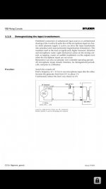
read enclosed , same applies - you just need (gradually) to bang it (point of signal xformer output) rail to rail (Vpp) and back to zero ..... and that's it (taking in account that there is some stage preceding xformer itself)
what amount of DC would cause permanent magnetizing of core certainly depends of actual xformer ...... though , I don't think that even manufacturer can give you exact values , covering all possible scenarios
NB - considering that there is preceding stage , amp must be on while performing process , but be sure that there is no load on output
personally , I believe that I would never practice that with my amps
Attachments
Ok......the latest post here is #2106.....so therefor I thought #3053 must be in the future.....the one I write now is #2107....or what number do you see?
OK....my fault…..#3053 in the other M2 thread….will have a look.....
What kind of transformer do you guys use in US? Also, does M2X need matched transistors for main board or any input boards? I'm planning to build Mountain View and Tucson. I'm new to solid state world and clueless. I understand reading about ACA amp that it needs matched transistors.
Hi imnewbie, welcome!
Most US builders of M2x purchase a toroidal power transformer from Antek in New Jersey, because shipping is so much cheaper than from non-US sellers. You want one with two secondaries, each secondary 18VAC. The two that I recommend are "AS-3218" (300 VA) and/or "AS-4218" (400VA). If they have the 300VA in stock, buy it. If they don't, buy the 400VA.
Nothing on M2x requires matched transistors EXCEPT perhaps the Ishikawa daughter card. For that you need advice from more experienced Toshiba JFET wranglers than me. For the amp main boards, and for the other four daughter cards, no matching is necessary.
Nevertheless you might find M2x builders who feel that although it's not necessary, matching nevertheless does no harm and possibly some good, so why not.
Nevertheless you might find M2x builders who feel that although it's not necessary, matching nevertheless does no harm and possibly some good, so why not.
Thank you sir. I'm just a little overwhelmed about building my first SS. Tube amps are so easy compared to this.
Is it even possible finding matching transistors for main board and input boards other than Ishikawa? Just wondering if anyone has found source(s) that sell something like that.
You’ll find that the first watt amps are actually easier once you’ve done one. 🙂 Also, no matching required on the ACA.
@imnewbie. There is a recent thread by another builder in a very similar situation.
A Noob’s First First Watt - M2x
A Noob’s First First Watt - M2x
With my M2x build it is my intention to use rail fuses. One for +22 VDC and one for -22 VDC. I will use the F-type fuses. E.g. 2A or 3.15A. I build mono blocks so fuse rating is for one board only. I have about 1/3 Farad in each PSU so I want to avoid all that energy going into the amp board in case of a failure. I have understood (also by reading the schematic) that bias will drop immediately to zero if just one rail fuse burns. Then output voltage will drop to zero so I don't get DC at speaker output. I don't see many use rail fuses? …..why? ….because it raise the impedance of PSU a little bit? …..does production Pass Lab or Firstwatt amps use rail fuses?
What is for and against?
What is for and against?
I have a shared (not dual mono) PSU in my M2x and I fitted rail fuses too. For safety I decided to put these vinyl condoms over the fuse holder
Fuse Covers: Cylindrical Fuse, 2AG, 3AG, 5mm Fuses: Keystone Electronics
so a dropped screwdriver or wayward bare wire can't touch the exposed metal at either end of the fuse. Mouser sells them, part number 534-3527C.
I also fitted ten ampere rail protection diodes after the fuses, as discussed in Cordell section 15.3 (the same section that covers rail fuses). I chose axial lead diodes, part number 10A07
Ok....thank you for the information.
Protection diodes I have not considered but will look at it.
Protection diodes I have not considered but will look at it.
I had the amp out of the rack for a quick checkup. All seems right with the world.
My willpower took a slide. I swapped the Tucson for the Mountain View. I've changed my mind (shocking!) - I want to try all the IPSs over the next few days to see if they all function properly.
A question for the group. I am trying to get my Ishikawa boards ready for installation. The pots I have seem to neither have a center detent nor a "click" at either end of the range. Is there a measurement point on the board with the pots installed to "center" them? Any help is appreciated. My review of the schematic still leaves me scratching my head, but I'm sure it's obvious to many. Any help is appreciated.
I'll have someone around next week that may be able to help with some blind (but not double-blind) IPS swapping.
Jim said, this is a "smile inducing amp". Well-said! 😀
You could use your Digital multimeter to measure the resistance between the pins and ensure you are at the middle position. Can be a bit tedious, but it will work for sure. Right?
- Home
- Amplifiers
- Pass Labs
- The diyAudio First Watt M2x