Regarding transistor orientation on Mountain View: one side has a silkscreen with some numbers on it and the other side has a small circle with an A in it. I am assuming that the silkscreen side is the front and should be opposite the PCB double line silk screen. If so, I have a bit of desoldering to do.
Regarding transistor orientation on Mountain View: one side has a silkscreen with some numbers on it and the other side has a small circle with an A in it. I am assuming that the silkscreen side is the front and should be opposite the PCB double line silk screen. If so, I have a bit of desoldering to do.
I am looking at my completed Mountain View board right not, and I d not see a circle with an "A" in it. So I must assume the "A" is being covered by a capacitor.
All of the boards should have the parts installed on the same side the name of the board.
The builders notes that are in the .zip linked in post #1 gives specific directions on orienting the transistors.
Hope this helps, a pic might be nice
-Josh
See page 1 of this thread, post#2. Third pic shows a nice closeup of the Mtn View stuffed and unstuffed. However, I don't see any inscribed "A" on the pic, nor on my own boards.
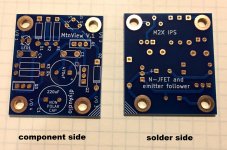
Here is the Mountain View PCB showing both the component side and the solder side. These boards were purchased from the diyAudio store. The epoxy fiberglass is blue colored.
There is a circle on the component side silkscreen, in white paint, where the (cylindrical) light emitting diode "LED1" is stuffed and soldered.
Click on the image and then click on the white cross at bottom left, to see it full size & undistorted.
_
There is a circle on the component side silkscreen, in white paint, where the (cylindrical) light emitting diode "LED1" is stuffed and soldered.
Click on the image and then click on the white cross at bottom left, to see it full size & undistorted.
_
Attachments
I just realized that wcwc is probably referring to the "silkscreening" on the transistor itself...
From the builders notes
From the builders notes
2. Transistor Orientation. Bipolar transistors Q1‐Q3 are encased in medium power
packages called TO‐126. These three parts are marked on the PCBoard silkscreen
as rectangles. Each rectangle has a double line along one of its four edges. That
double line signifies the REAR of the transistor, i.e., the side where the part
number does NOT appear. The FRONT of the transistor is the side where the part
number DOES appear.
I was talking about the transistor silkscreen. Looks like I mounted them all backwards. So I have some desoldering to do.
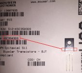
Fortunately the phrase "part number" helps you decide which side of the TO-126 is the front and which side is the back. Here is the shipping bag in which Mouser.com sent me 30 pieces of KSC3503DS transistors. I laid one of the transistors upon the label of the bag, with the front of the transistor facing the camera. You can see its "part number" quite cleary. BTW my transistor part numbers are laser etched, not silkscreen printed.
_
_
Attachments
It was my fault for soldering up the Mountain View board without reading the notes for the board. If I had the transistors would be in correctly. I had the right orientation for the LED. Gives me a chance to practice some desoldering.
M2X C0
Hi,
In text description of the use of C0, which I believe I do want, it states C0 is 220pF and 50v. The BOM for the board has a mouser part number which is 220 pF and 100v. Which is correct, and is there any directionality/polarity on this and C1?
Thanks
M2X Amp Main Board: Notes for Builders (rev 01)
5. Capacitor “C0” is not present in the original M2 amplifier by Nelson Pass. The M2 owner’s manual explains that this makes it easier for tube preamps to drive an M2. However C0 does perform a useful function: together with input resistor R1, it filters (removes) unwanted radio frequency interference. The transformer’s HF rolloff helps too. I suggest that if you’re absolutely certain you’ll never drive M2X with a tube preamp, never ever ever, consider soldering C0 into the amplifier board. C0 is a NP0/C0G ceramic capacitor, 50 volts, 220 pF. Of course you can cut it out later if you change your mind.
.
Hi,
In text description of the use of C0, which I believe I do want, it states C0 is 220pF and 50v. The BOM for the board has a mouser part number which is 220 pF and 100v. Which is correct, and is there any directionality/polarity on this and C1?
Thanks
As long as you make CERTAIN to buy a capacitor whose dielectric is NP0/C0G for capacitor C0, its voltage rating can be anything above 40 volts. So I suggest you get price and availability quotes from Mouser.com or whoever is your preferred vendor, for both 50V and 100V capacitors. Then choose whichever one is on the shelf. If they're both on the shelf and similarly priced, buy the higher voltage cap. If they're both on the shelf and priced very differently, buy the cheaper one. Just be CERTAIN it's NP0/C0G.
*If some dunce applies an input signal greater than 40V to your M2 amplifier, not only will this damage C0, it will also damage the input stage daughter card. Voom! Your $50 Toshiba JFETs on Ishikawa just joined the bleeding choir invisible.
_
*If some dunce applies an input signal greater than 40V to your M2 amplifier, not only will this damage C0, it will also damage the input stage daughter card. Voom! Your $50 Toshiba JFETs on Ishikawa just joined the bleeding choir invisible.
_
Attachments
Well I was able to desolder the transistors, turn them around, and resolder the transistors. Now we have to see if the transistors still work or if I got them too hot.
As long as you make CERTAIN to buy a capacitor whose dielectric is NP0/C0G for capacitor C0, its voltage rating can be anything above 40 volts. So I suggest you get price and availability quotes from Mouser.com or whoever is your preferred vendor, for both 50V and 100V capacitors. Then choose whichever one is on the shelf. If they're both on the shelf and similarly priced, buy the higher voltage cap. If they're both on the shelf and priced very differently, buy the cheaper one. Just be CERTAIN it's NP0/C0G.
_
Thanks 🙂
Is it true that C0, C1, CB3 do not have a specific polarity? i.e. they can be put in either direction?
Last edited:
So, get this...
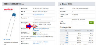
Mouser diagram for M2X RV1 listed part number 64WR5KLF

vs. Digikey diagram for the same part number

Actual part in hand from Mouser order has pins offset 🙁 The pins are pretty short. Is it worth trying to bend them? or better to wait for new order?
Mouser diagram for M2X RV1 listed part number 64WR5KLF
vs. Digikey diagram for the same part number
Actual part in hand from Mouser order has pins offset 🙁 The pins are pretty short. Is it worth trying to bend them? or better to wait for new order?
Cool - Thanks. Looks like the BOM part number for the M2X Main board RV1 is not correct. The INLINE pin arrangement which fits the PCB through holes should be 64YR5KLF
Yep, had the same issue with RV1. Don't think I am going to try to bend the pins. I will just order a new part. I screwed up ordering a few of the resistors also. They were a bit too big to fit.
that's interesting. I'm using a Bourns 3296W which is the in-line version. I was under the assumption that W, Y and Z configurations were something of an industry standard but it seems I was wrong. Hopefully someone else might have a better answer.
I thought I would try the Norwood daughter board and already received the parts. After trying my beginner hand at some practice surface-mounting, I am [re-]thinking I better build up the Mountain View or Austin first. Since I am re-ordering... Anyone have experience with either they care to share? Furthermore, with the resistor values in BOM, are the all 1/4 (.25) W?
Yep, had the same issue with RV1. Don't think I am going to try to bend the pins. I will just order a new part. I screwed up ordering a few of the resistors also. They were a bit too big to fit.
The ones I ordered also ended up having a straight line pinout. I simply bent the leads to match the board and they worked just fine.
- Home
- Amplifiers
- Pass Labs
- The diyAudio First Watt M2x