If we designed Class A amps to be compact, low cost, and cool-running - they would look like computer server racks.
Hmm, very much doubt it.
If you visit the hub of let's say a satellite earth station you'll immediately notice the heat generated there and the massive air conditioning employed.
Nothing runs Class A in that environment.
Unfortunately Class A, low cost and cool running cannot coexist.
But I still admire yours and other people efforts to find a balance in all this.
I have an OC'd I7-5960X, just a couple more cores than the 5930K, and it's water cooled. Yeah, it is amazing how much heat these relatively small processors can churn out. The 140W figure is total dissipated power, millions of tiny transistors drawing microamps or something, 2011 contact points on the CPU to distribute the amperage.
But as Joshua mentioned, his water cooling quit working so he went to fan/heatsink.
I've had fans quit, too.
I've never had a passive heatsink quit. 😀
But as the amp v computer analogy shows, there's more than one way to skin a cat. Use whatever method suits your situation and have some fun. There are passively cooled computers and fan cooled amps out there right now, it's already been contemplated and acted upon by others before us.
Also I am not arguing that forced cooling does not work, it does, but there are specific issues with it and one is reliability.
That is one of many reasons why Pass Labs amps employ monstrous heatsinks.
...
Best,
Stan
Also, I wouldn't be surprised if a good chunk of PL's customers will
consider any mechanical noise from an amplifier to be unacceptable.
I have finally got around to ordering my parts, Mouser have most caps on back order and the chassis accessories pack will not ship until late January, plenty of time to read and study this thread.
The one thing I do have is a blue LED 🙂
The one thing I do have is a blue LED 🙂
My first M2x used a Purple LED as a pilot light Jameco Electronics link. It took a couple of revisions IN THE LISTENING ROOM to get the brightness just right. All of the lab experiments performed on the bench beforehand, not in the amplifier chassis, gave results that were "close but not correct".
Maybe other colors / other builders , will have better results.
Maybe other colors / other builders , will have better results.
Hmm, very much doubt it.
If you visit the hub of let's say a satellite earth station you'll immediately notice the heat generated there and the massive air conditioning employed.
Nothing runs Class A in that environment.
Unfortunately Class A, low cost and cool running cannot coexist.
But I still admire yours and other people efforts to find a balance in all this.
You must have missed this a few posts back. This is the Aksa Lender PMOS Hybrid (ALPHA) 55w Class A amp that runs using $60 worth of CPU coolers with PWM fans to cool 400w of dissipation. Mosfet runs at 38C body temp. Fins are running at 28C. This is the silent lowest speed setting. If you look at Juntuin’s implementation of same amp, it sort of resembles a computer case.
Satellite ground system rooms are mostly rack mount servers. Still uses cpu coolers but you need massive AC to get rid of the ejected heat from the racks. Of course computers don’t run Class A, they are not audio amps. But the heat rejected is the heat rejected as measured in watts.
But enough talk about heatsinks and cooling in this thread and get back to the M2X.
Last edited:
But enough talk about heatsinks and cooling in this thread and get back to the M2X.
It's a fair topic for the M2x, since not all of us are using the cookie cutter case & sinks from the store. Forced air cooling, while not as sexy as big chunks of shapely aluminum with all-natural convection, may be a necessary evil for a budget build.
But we ARE eager to see how your Melbourne test works out.
Most "consumer" CPU's nowadays are in the 10w to 35w range. However, professional server/workstation Xeon 7150 dual-core processors (604 socket 3.5GHz) at one point ran as high as 150w! Look at page 75 of the spec sheet:
https://www.intel.com/Assets/PDF/datasheet/314553.pdf
This is a really simplistic back of the envelope type calculation, I am sure there are some parts of the CPU that are off or not used during certain operations, but this will be in the rough factor of 10 ballpark I think.
The Xeon 7150 has 1.9B transistors, and assuming all are in use at 100% CPU demand, that's 79nW dissipation per transistor.
And as far as amps using P=IV, assuming 3.5v, I=P/V=79nW/3.5v=2.2nA per transistor. A tiny tiny current to be sure, but enough to activate a 22nm process CMOS transistor.
Neither the onboard static RAM nor the onboard dynamic RAM can possibly have 100% of active devices switching simultaneously. As a few minutes of concentrated thought will verify.
(source: have designed microprocessor chips)
(source: have designed microprocessor chips)
Also, I wouldn't be surprised if a good chunk of PL's customers will
consider any mechanical noise from an amplifier to be unacceptable
I think people like the hardware too. There's a bit of a wow factor there as well with large heat sinks.
Audiophile don't like waifie hardware.
"Weight is sign of reliability. If it doesn't work, you can always hit him with it." - Boris the Blade
Attachments

Last edited:
It's not uncommon to have variable speed fans whose RPM increases when temperature @ the temperature sensor(s) goes up, and whose RPM decreases when temperature decreases. The first one I designed into a commercial product used an LM358, an NTC thermistor, and a TIP41 to drive the fan(s). It was a lot cheaper to roll your own on the PCB than to buy a fan with integrated variable speed controller.
It would be easy to add "how loud is the music playing" to the fan control circuitry, and include two different Schedules of fanspeed vs temperature, one for when the music is loud and another for when the music is not-loud. That way you don't crank up the fan unless loud music will mask the noise.
Of course this would only be beneficial on class-AB power amps; class A power amps run the hottest when the music is silent.
You could do this with a pair of miniature microphones, one listening to the interior of the chassis and one listening to the exterior. Or you could monitor the amplifier's output voltage and/or output current (a la Aleph). Or both.
I think that even at the lowest speed setting (at least on my 120mm and 80mm PWM fans), the max temperature of the heatsink while fan-cooled in Class A never gets too hot, and thus the fans continue to run at silent mode (in-audible at 12in away with no music playing, my sound meter measured 35db SPL or bottom of its limit at 12in). I am using a commercial off the shelf (COTS) PWM fan controller that has a thermistor temp sensor that speeds the fan up. The setpoint for the speed-up is selectable via dip switch programming, and the minimum speed can be set with a trim pot. This $3.12 controller board will power up to 3 fans using a 12v input supply. It even has an audible alarm for fan stall. Tough to DIY something this feature packed and easy to use for so little.
12V PC CPU 4 Wire Fan Temperature Control PWM Speed Control Module W/ Alarm | eBay

Description:
12V PC CPU 4 Wire Fan Temperature Control PWM Speed Control Module W/ Alarm | eBay
Description:
Support all within 12V 5A fans, synchronous rectifier output, high efficiency! Even if a large current work does not require additional heat sink! A plurality of fans can be used in parallel (total current does not exceed 5A), supports automatic temperature control and manumotive speed control, temperature control speed with four temperature zones for setting up, easy to apply in a variety of applications! It can be opened with a three-wire fan monitoring function (stall warning).
Working voltage: DC12V
Circuit load capacity: maximum current per output 5A, the bus currents up 9A
Output Range: The first channel 20% -100%, or 40% -100% (TFL = ON)
The second channel and the third channel 10% -100%
(Note: Above range only for PWM range, the actual control effect will vary depending on the fan.)
Temperature probe parameters: 50K B = 3950
Thermostat temperature zone error: error depending on the temperature probe, generally 3-5%
Stall alarm minimum speed: 700-800 rpm
Function setting switch Description:
TFL (No. 1): The lowest temperature channel PWM setting, when ON state FAN1 PWM minimum is 40%, when OFF the minimum PWM of FAN1 is 20%.
TP1 TP2 (No. 2,3): Temperature channel control temperature zones are interpreted as follows (need to used with the temperature probe):
TP1 TP2 Accelerating temperature Full speed temperature
OFF OFF 35℃ 45℃
ON OFF 40℃ 55℃
OFF ON 50℃ 70℃
ON ON 60℃ 90℃
Last edited:
Neither the onboard static RAM nor the onboard dynamic RAM can possibly have 100% of active devices switching simultaneously. As a few minutes of concentrated thought will verify.
(source: have designed microprocessor chips)
Thanks, Mark. You are the perfect person to give us some real numbers. How many amps of current does a typical AMD 100w class CPU draw? What is dissipation per little MOSFET gate?
The 12v and 5vdc supplies for PC's are in the 10A-20A range I think. I had a dual AMD workstation from HP that had a 450w power supply. Some of that went to the graphics card which put out some heat as well.
xrk971
but what do you think about the m2x?
When I think that I have to translate each post to make my M2X.
But you are free to do so.
Fortunately I'm waiting for the edcor transformer to finish, so I have time to read everything.
Otherwise how do we insert a photo in the forum?
Thank.
but what do you think about the m2x?
When I think that I have to translate each post to make my M2X.
But you are free to do so.
Fortunately I'm waiting for the edcor transformer to finish, so I have time to read everything.
Otherwise how do we insert a photo in the forum?
Thank.
Frenchy,
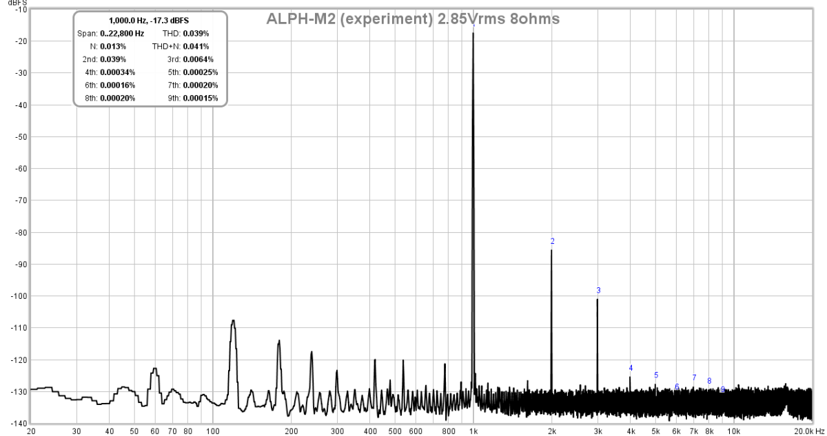
I do not as of this moment have an M2X yet. I have a Teabag M2, which I modified by bypassing the Edcor and drove it with an externally mounted Aksa Lender preamp (same preamp as the "Melbourne" M2X daughterboard). This is described here:
https://www.diyaudio.com/forums/sol...pass-hybrid-m2-alph-m2-amp-3.html#post5604098
I found that it sounds great. This was the inspiration to make an M2X DB form factor for others to try the same preamp easily. You can of course, leave the Edcor in place, and it will work. But it is also easy to try without the Edcor and see what sounds best to your ears.
Here is FFT without Edcor in place:
I ordered the M2X boardset and it should be here in a few days. The mew Melbourne DB PCBs should also arrive in a week or so and I will build them all up and test it out to make sure it works before offering the Melbourne in a separate GB.
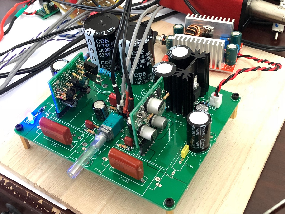
So basically I am taking the Aksa Lender preamp (shown here in stereo with built in power conditioning cap Mx and CRCRC):
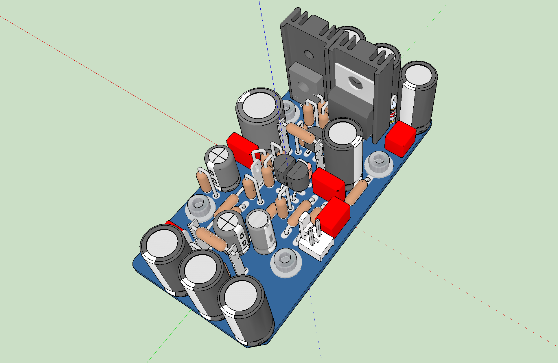
And shrinking it down to one channel that looks like this:
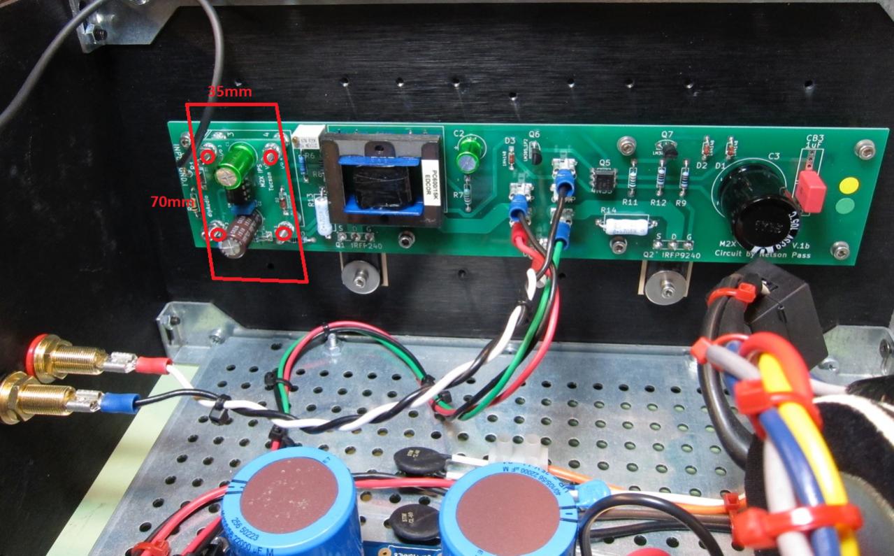
So that it can fit here:
Both through hole and SMT versions of the Melbourne will be offered.
I think the M2X is an excellent modular design amp and perhaps more amps should be offered this way with one's choice of input stage and choice of output stage. Within the Pass Labs, there are about 3 or 4 output stage topologies that come to mind: opto-coupler controlled bias push-pull (like M2), there is the Aleph dynamic CCS, there is the F5 style push pull with NTC bias regulation, and probably many others including simple MOSFET follower like the MoFo. They all have their signature sound. With the Aleph having been modifield to accept the Aksa Lender front end and have a PMOS on the output in the so called, ALPHA amp. I look forward to building the M2X and listening to the various input stages.
I do not as of this moment have an M2X yet. I have a Teabag M2, which I modified by bypassing the Edcor and drove it with an externally mounted Aksa Lender preamp (same preamp as the "Melbourne" M2X daughterboard). This is described here:
https://www.diyaudio.com/forums/sol...pass-hybrid-m2-alph-m2-amp-3.html#post5604098
I found that it sounds great. This was the inspiration to make an M2X DB form factor for others to try the same preamp easily. You can of course, leave the Edcor in place, and it will work. But it is also easy to try without the Edcor and see what sounds best to your ears.
Here is FFT without Edcor in place:
I ordered the M2X boardset and it should be here in a few days. The mew Melbourne DB PCBs should also arrive in a week or so and I will build them all up and test it out to make sure it works before offering the Melbourne in a separate GB.
So basically I am taking the Aksa Lender preamp (shown here in stereo with built in power conditioning cap Mx and CRCRC):
And shrinking it down to one channel that looks like this:
So that it can fit here:
Both through hole and SMT versions of the Melbourne will be offered.
I think the M2X is an excellent modular design amp and perhaps more amps should be offered this way with one's choice of input stage and choice of output stage. Within the Pass Labs, there are about 3 or 4 output stage topologies that come to mind: opto-coupler controlled bias push-pull (like M2), there is the Aleph dynamic CCS, there is the F5 style push pull with NTC bias regulation, and probably many others including simple MOSFET follower like the MoFo. They all have their signature sound. With the Aleph having been modifield to accept the Aksa Lender front end and have a PMOS on the output in the so called, ALPHA amp. I look forward to building the M2X and listening to the various input stages.
Last edited:
Would it be possible to avoid the coupling cap between preamp and irfp buffer stage? Something like in the alph-m2 hybrid trad schema but keeping the mosfet bjt output stage of the preamp?
"Weight is sign of reliability. If it doesn't work, you can always hit him with it." - Boris the Blade
I like it.
Exactly my thought.
Would it be possible to avoid the coupling cap between preamp and irfp buffer stage? Something like in the alph-m2 hybrid trad schema but keeping the mosfet bjt output stage of the preamp?
The output coupling cap on the Melbourne is optional. It is nominally 0Vdc output. Even with Edcor bypassed, you could even couple directly to the output stage without C2.
I think the M2X is an excellent modular design amp and perhaps more amps should be offered this way with one's choice of input stage and choice of output stage. Within the Pass Labs, there are about 3 or 4 output stage topologies that come to mind: opto-coupler controlled bias push-pull (like M2), there is the Aleph dynamic CCS, there is the F5 style push pull with NTC bias regulation, and probably many others including simple MOSFET follower like the MoFo. They all have their signature sound. With the Aleph having been modifield to accept the Aksa Lender front end and have a PMOS on the output in the so called, ALPHA amp. I look forward to building the M2X and listening to the various input stages.
I bought one of your ASKA Lender preamp boards to try on the front end of the F4. I'm building an all Toshiba M2 (Got some matched Toshiba JFETS and 2SK1530/2SJ201 MOSFETS), then I'll do the F4/ASKA. Been gathering parts forever, finally got off my duff and bought a couple of 4U Chassis to get it all together (no fans, sorry 😀).
- Home
- Amplifiers
- Pass Labs
- The diyAudio First Watt M2x