Nope, no mockery, merely extrapolating to other possibilities.
The chassis that I used to build an M2x, can be turned on is side (rotated 90 degrees) and rested on the left-channel heatsinks / right channel heatsinks without bending or deforming them. Even while supporting the weight of the entire amplifier. This means the amplifier PCB is now horizontal, parallel with the floor, making it easier for me to remove the fasteners.
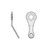
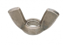
Speaking of other possibilities, you could consider replacing the star washers with Keystone 7318 lugs, Mouser part # 534-7318. Now they're bigger so they're easier to find when dropped. Or you could connect a colorful insulated wire to each of them, and solder that wire to the main PCB. This gives redundant electrical connection and impossible-to-lose lugs. If you switched to wing-nut style M3 fasteners instead of hex nuts, those might be harder to lose too. A dollop of hot glue on the bolt protruding from the wing-nut, would provide a safety attachment-seal that's also removable later.
The chassis that I used to build an M2x, can be turned on is side (rotated 90 degrees) and rested on the left-channel heatsinks / right channel heatsinks without bending or deforming them. Even while supporting the weight of the entire amplifier. This means the amplifier PCB is now horizontal, parallel with the floor, making it easier for me to remove the fasteners.
Speaking of other possibilities, you could consider replacing the star washers with Keystone 7318 lugs, Mouser part # 534-7318. Now they're bigger so they're easier to find when dropped. Or you could connect a colorful insulated wire to each of them, and solder that wire to the main PCB. This gives redundant electrical connection and impossible-to-lose lugs. If you switched to wing-nut style M3 fasteners instead of hex nuts, those might be harder to lose too. A dollop of hot glue on the bolt protruding from the wing-nut, would provide a safety attachment-seal that's also removable later.
Attachments
Secondly, maybe some sort of "conversion" brackets for sinks like Vfet uses?
Any idea what sort of thermal resistance this junction adds?
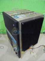
I'm scavenging as much as possible to build, so additional mounting possibilites may be helpful in creating a suitable case. BUT, my scavenged heatsink will not be generous ~ 0.3K/W (per channel) if I'm lucky. Sink scavenged from an old industrial controller:
Attachments
All good then 🙂
I don't have access to the Passlabs sink.
In a previous life, I was a professional furniture maker, and I am a competent hobby machinist, so I have many options. Raw materials are quite expensive, so the cost savings will be under $120.00 assuming I buy DIYAudio sinks in place of buying a Dissapante 400mm alu case.
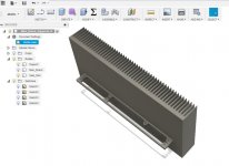
I made a quick drawing in Fusion 360 since a pic is often better than words. This could be fabricated with nothing more than a drill and a coping saw from resin board or aluminum, and is a trivial job on a milling machine.
I don't have access to the Passlabs sink.
In a previous life, I was a professional furniture maker, and I am a competent hobby machinist, so I have many options. Raw materials are quite expensive, so the cost savings will be under $120.00 assuming I buy DIYAudio sinks in place of buying a Dissapante 400mm alu case.
I made a quick drawing in Fusion 360 since a pic is often better than words. This could be fabricated with nothing more than a drill and a coping saw from resin board or aluminum, and is a trivial job on a milling machine.
Attachments
Russellc,
You can get clone case from China - has horizontal fins but will still need an L bracket heat spreader to mount the board horizontally. I find mounting boards vertically a very good option as it reduces chances of metal bits falling into circuit and shorting things out.
B 048 CNC All Aluminum Cabinet Chassis Case Box Cabinet for DIY Audio Power Amplifier 430mm*430mm*170mm 430*430*170mm-in Amplifier from Consumer Electronics on Aliexpress.com | Alibaba Group
Any idea what sort of thermal resistance this junction adds?
I'm scavenging as much as possible to build, so additional mounting possibilites may be helpful in creating a suitable case. BUT, my scavenged heatsink will not be generous ~ 0.3K/W (per channel) if I'm lucky. Sink scavenged from an old industrial controller:
None. You can see (if you havent already that is) in 6L6's build guide how they attach them with goop and appears to work fine, waiting for them to get back in stock for my V-Fet build.
Russellc
Russellc,
You can get clone case from China - has horizontal fins but will still need an L bracket heat spreader to mount the board horizontally. I find mounting boards vertically a very good option as it reduces chances of metal bits falling into circuit and shorting things out.
B 048 CNC All Aluminum Cabinet Chassis Case Box Cabinet for DIY Audio Power Amplifier 430mm*430mm*170mm 430*430*170mm-in Amplifier from Consumer Electronics on Aliexpress.com | Alibaba Group
Well, I have just been using either the Deluxe 4 or Deluxe 5 chassis from the store, since these boards as well as all the ones I have used (except original F5 with Peter Daniels boards) are designed to fit the pre drilled pattern...more costly than DIY, but way easier! It was good to learn that I could drill and tap if need arises. I still find an occasional aluminum scruddle here and there!
Russellc
...waiting for them to get back in stock for my V-Fet build...
I think you will be waiting for a long time, I want some too; click the link 🙁
404 Not Found – diyAudio Store
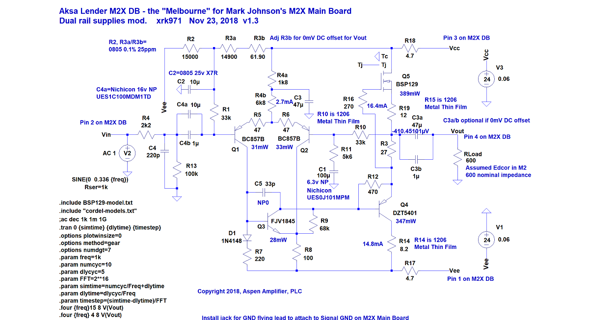
TH Melbourne DB
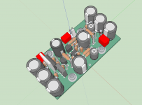
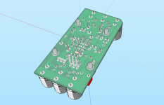
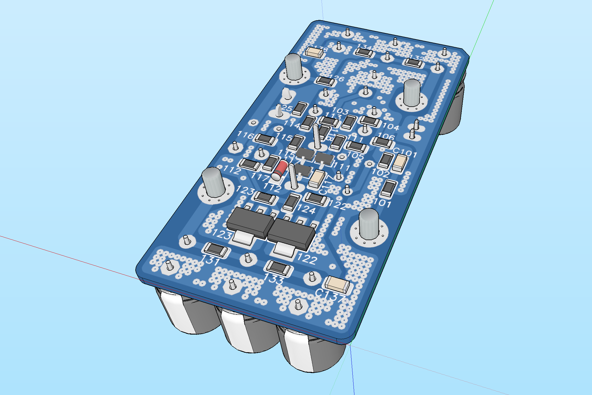
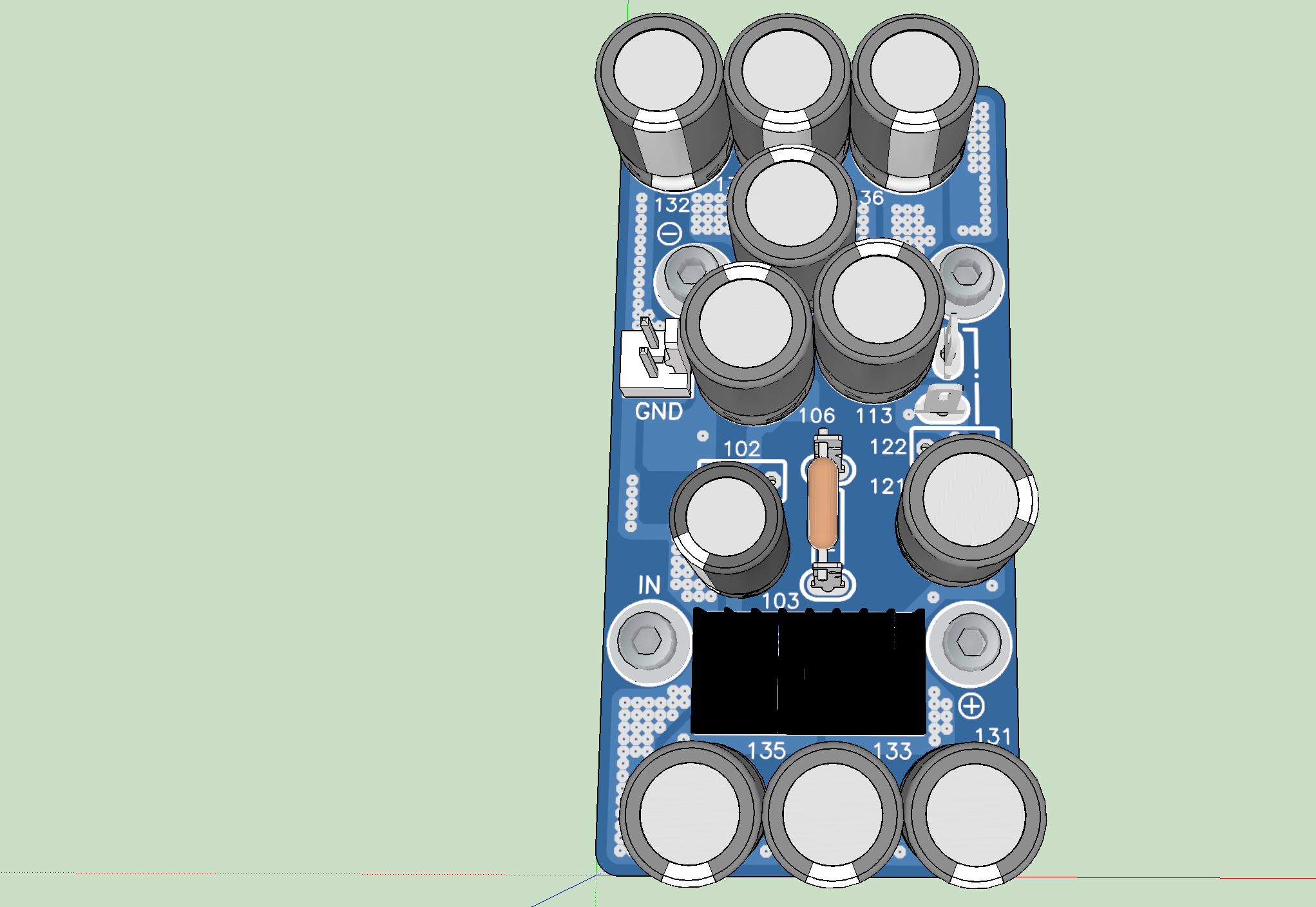
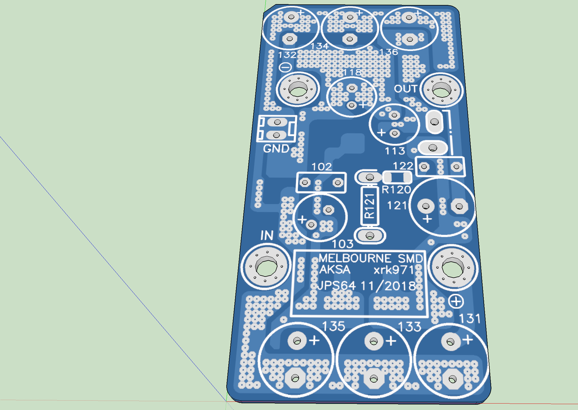
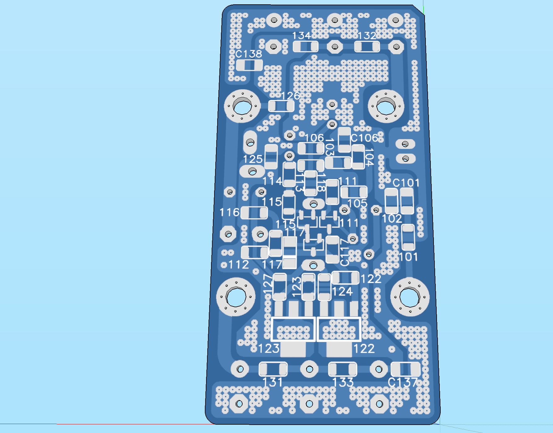
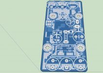
Here are some preliminary renders of the through hole version. I think we can reduce the size of the huge feedback shunt cap as it looks like a 100uF 63v Silmic II shown, when all that is needed is a 100uF 6.3v (NP preferable).


Here are some preliminary renders of the through hole version. I think we can reduce the size of the huge feedback shunt cap as it looks like a 100uF 63v Silmic II shown, when all that is needed is a 100uF 6.3v (NP preferable).
Attachments
All good then 🙂
I don't have access to the Passlabs sink.
In a previous life, I was a professional furniture maker, and I am a competent hobby machinist, so I have many options. Raw materials are quite expensive, so the cost savings will be under $120.00 assuming I buy DIYAudio sinks in place of buying a Dissapante 400mm alu case.
I made a quick drawing in Fusion 360 since a pic is often better than words. This could be fabricated with nothing more than a drill and a coping saw from resin board or aluminum, and is a trivial job on a milling machine.
Would be nice....I wasnt thinking through, looks like your idea just mounts the boards horizontally with mosfets attaching as usual. This eliminates the thermal junction problem...simple bracket could be made that could be attached to existing store chassis heatsink...now I understand your desire to have card designed as you stated.
Thinking through further, it would make pot adjustments easier, but in terms of ease to get to underside of board....not so much at least with DIY store case. Once I remove bottom, would still need to remove inner perforated pan and transformer. I guess access could be cut out of the pan under boards, then remove bottom panel, and access could be had to underside of boards!
Russellc
Bracket could be designed to have pre drilled pattern so store boards would fit, attach to pre drilled board pattern holes in Deluxe heat sink and still line mosfets up with existing pre drilled mosfet mounting holes in deluxe chassis heatsinks....The store could sell these I'm thinking, with pre cut perforated Pans for under board access...
Sorry about off topic brain fart, must rest tiny brain.
Russellc
Sorry about off topic brain fart, must rest tiny brain.
Russellc
....I wasnt thinking through, looks like your idea just mounts the boards horizontally with mosfets attaching as usual...
I use small(ish) L brackets with spacers between the PCB.
If you flip the whole assembly and have the solder side on top, you have easy access for modding, fitting the new components might be a little fun(!) though.
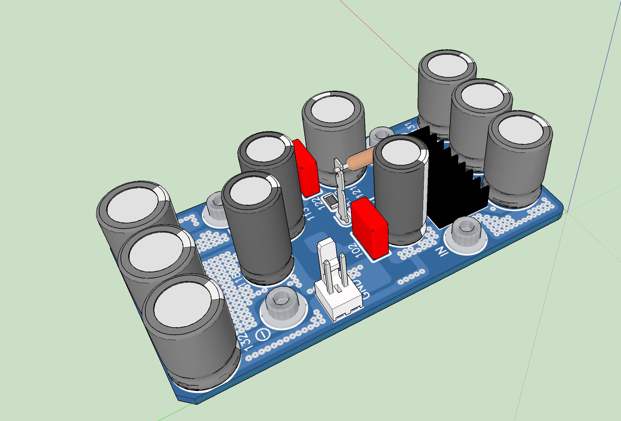
More progress on Melbourne DB SMT version. JPS64 is doing a superb layout for us here. Stick-on heatsink now added to help keep outputs cool.
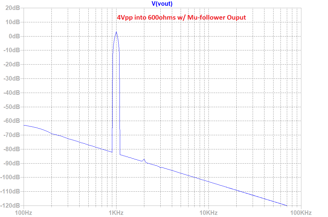
A Mu-follower output was suggested by Paul Bysouth and was implemented by taking the 39R source resistor and replacing with 12R and 27R and putting output node in between. This had effect of reducing the THD from 0.014% down to 0.0039% for same 4Vpp into 600ohm load.
Code:
Harmonic	Frequency	 Fourier 	Normalized	 Phase  	Normalized
 Number 	  [Hz]   	Component	 Component	[degree]	Phase [deg]
    1   	1.000e+03	2.051e+00	1.000e+00	    0.11°	    0.00°
    2   	2.000e+03	6.065e-05	2.957e-05	  144.21°	  144.09°
    3   	3.000e+03	2.924e-05	1.426e-05	  179.98°	  179.87°
    4   	4.000e+03	2.401e-05	1.170e-05	 -179.76°	 -179.87°
    5   	5.000e+03	1.921e-05	9.365e-06	 -179.94°	 -180.05°
    6   	6.000e+03	1.600e-05	7.802e-06	 -179.95°	 -180.06°
    7   	7.000e+03	1.372e-05	6.688e-06	 -179.95°	 -180.07°
    8   	8.000e+03	1.200e-05	5.852e-06	 -179.96°	 -180.07°
    9   	9.000e+03	1.067e-05	5.202e-06	 -179.96°	 -180.08°
   10   	1.000e+04	9.602e-06	4.681e-06	 -179.97°	 -180.08°
   11   	1.100e+04	8.729e-06	4.256e-06	 -179.97°	 -180.08°
   12   	1.200e+04	8.002e-06	3.901e-06	 -179.97°	 -180.09°
   13   	1.300e+04	7.386e-06	3.601e-06	 -179.98°	 -180.09°
   14   	1.400e+04	6.859e-06	3.344e-06	 -179.98°	 -180.09°
   15   	1.500e+04	6.401e-06	3.121e-06	 -179.98°	 -180.09°
Total Harmonic Distortion: 0.003948%(0.047804%)
Attachments

Melbourne SMT v1.3
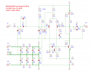
Latest Schematic for SMT version 1.3 - all 1206 resistors for easy soldering:
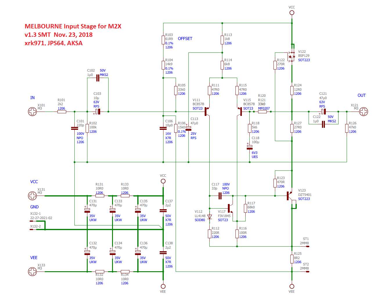
Latest Schematic for SMT version 1.3 - all 1206 resistors for easy soldering:
Attachments


Last edited:
Kind of surprising there's no trim mechanism to tune the current of depletion mode current source V122.
Also kind of surprising to see R101, R102, and C101 included on the daughterboard since they already exist on the motherboard, as shown in post #1 schematics.
Also kind of surprising to see R101, R102, and C101 included on the daughterboard since they already exist on the motherboard, as shown in post #1 schematics.
Hi Mark Johnson,
No trim needed for bias - it is pretty steady and consistent with source resistor(s) used to set it. As for the input R and C, I included so that this module can be used as a standalone front end on another amp. Or as a stand-alone preamp. One can always use a jumper on R101 and leave R102 and C102 unpopulated.
No trim needed for bias - it is pretty steady and consistent with source resistor(s) used to set it. As for the input R and C, I included so that this module can be used as a standalone front end on another amp. Or as a stand-alone preamp. One can always use a jumper on R101 and leave R102 and C102 unpopulated.

Looks like you have an LED in that Mountain View board on the left.
Hi Mark,
dBel84 was so kind that he send me a pair of those 🙂 huge thank to him!
- Home
- Amplifiers
- Pass Labs
- The diyAudio First Watt M2x