I f you lower the resistance below 12.5 kOhm the current goes up
(with constant 50V ).
50 V / 5000 Ohm = 0.01 A
50 V x 0.01 A = 0.5 W = 500mW
As a result from the higher amperes at the same voltage (50 V) the watts of the resistor have to get higher. 😕
(with constant 50V ).
50 V / 5000 Ohm = 0.01 A
50 V x 0.01 A = 0.5 W = 500mW
As a result from the higher amperes at the same voltage (50 V) the watts of the resistor have to get higher. 😕
Fortunately the 100 ohm and 221 ohm resistors in the M2x circuit schematic, emphatically DO NOT have 50 volts DC across them.
Hi Mark -
LOL! I truly appreciate the learning experience and copied your similar advice back in the "summer" into my build/learning guide. Where I got frustrated was that (seemingly) a very very similar nomenclature was used for parts that can be "rated" differently by Vishay. That's what was making me nuts. I sorted Mouser by 1/4 or 1/2W, and the spec sheets for the parts would not match the data in Mouser search tables or the product descriptions. The CMF60 "Industrial" resistors are all 1W. The CMF60 "Military" resistors are all 1/4W. Some 1/4W resistors (in product description and spec sheet) were showing up as 1/8W in Mouser.
You sir, are a gentleman and a scholar for attempting to teach an old dog....
Onto the learning and math... <starting up the way-back machine>
First had to make sure I understood the term power dissipation. I admit I looked it up. I recall it from early electronics that we lose / exchange current as heat across a resistor, but I wasn't completely sure.
Why - You've given the dissipation already. So you'd need resistors rated at 1/8W or 1/5W or better. Not sure what the fudge factor is or how the ratings are determined.
Keeping a resistor rated higher than that keeps it from burning up (depending on how they're rated) and allows them to hopefully operate at a fairly predictable resistance. Those specs are included on spec sheets. i.e. ppm / C
Moving on -
Current through the resistor would be 4mA for 50V across a resistor with a power dissipation of 200mW. (I think)
If I did it properly, then the resistance to dissipate exactly 200mW at 50V would be 12,5k. Since dissipation increases with resistance - 12.5k would be the lowest value. If I did that correctly, then I'll more than happily do it for the other combinations of 46V 200mW, 46V 175mW, and 50V 175mW. But, I think the "worst case" is 50V with the highest dissipation.
Why..
I would guess (and it's a WAG) that when designing a circuit we generally know the voltages we need for certain parts to operate properly. We also have parts that are sensitive to current (LEDs etc). We use resistors to get the current to where we need it for the part to operate (among many other reasons). If I have a circuit that needs both lower and higher currents in certain segments, we need properly-rated resistors for the voltage we intend to use to achieve the current we desire. If we don't want to give off too much heat (or burn up parts) or if parts simply aren't on this earth that for physical size or material constraints will operate within those ranges.. then it's very useful to know. I'm sure everyone would love a resistor that could lower the current w/o changing its resistance over a huge temp range while also not giving off any heat, but physics...
If that's wrong, I don't mind looking foolish. You took the time to teach, so I'll give my best answer no matter how it may look.
Edited to add - Well, I was too slow. I saw cubicincher's much more concise response and your explanation. I'll still leave my nonsense posted for .... posterity...
Last edited:
I do the power dissipation calculations for resistors all the time, really for most of the resistors I spec / buy, as I like to build up my own BOMs.
So, Ohm's law R=U/I and the power dissipation P=U*I is really all that's needed.
That leads to the two ways to come up with power dissipation: P=I^2*R or P=U^2/R.
The last few amps I have built have been solid-state with "Pass-ish" voltages. Right now I'm building the mental model / BOM for a nice little EL84 P-P tube amp I plan on building next, since I already have an overkill Aikido PSU that I can use for that ... building Wayne's linestage has freed up the Aikido PSU 😀.
So, working on a tube amp really throws you off regarding your feeling for resistor values and dissipation ... because now we're not talking voltages of around +/- 25V, but 250-350V DC 😛
Regards, Claas
The first thing you must do is buy a Mega328 component tester, WITH CASE ("SHELL"), from eBay. Shop around for the fastest shipping or the lowest price or the most beautiful photograph in the listing. Here are three listings chosen at random from eBay's 200+ listings:
Once you have received and learned how to use the Mega 328,
For every resistor that has a power rating listed in the M2x Bill Of Materials: buy that power rating!! (example: R14)
For every resistor that does not have a power rating listed in the Bill Of Materials: attempt to buy that resistance in a metal film resistor with 0.6W power rating.
If 0.6W is not available, attempt to buy that resistance in a metal film resistor with 0.5W power rating.
If 0.5W is not available, attempt to buy that resistance in a metal film resistor with 0.25W power rating.
If 0.25W is not available you are doing something very very wrong. Either shopping at the wrong website, or operating the website incorrectly, or both.
As long as you are buying metal film resistors the manufacturer / brand / series hardly matters at all. Make the decision by flipping a coin, or by buying the cheapest, or by relying on the advice of some stranger you once overheard, who proclaimed that Roderstein Resistors Rock and Sprague Resistors Suck!! I personally buy the cheapest.
Since I have a Mega328, I am not afraid to buy metal film resistors with color coded bands instead of letters and numbers printed on the resistor body. I follow 6L6's advice to measure every resistor before stuffing and soldering it. This prevents stupid errors like accidentally swapping R6 and R7. How do I measure resistance? With the Mega328 of course.
The Mega328 will save your hiney butt a thousand times, and allow you to build electronics successfully without memorizing the resistor color code.
Once you have received and learned how to use the Mega 328,
For every resistor that has a power rating listed in the M2x Bill Of Materials: buy that power rating!! (example: R14)
For every resistor that does not have a power rating listed in the Bill Of Materials: attempt to buy that resistance in a metal film resistor with 0.6W power rating.
If 0.6W is not available, attempt to buy that resistance in a metal film resistor with 0.5W power rating.
If 0.5W is not available, attempt to buy that resistance in a metal film resistor with 0.25W power rating.
If 0.25W is not available you are doing something very very wrong. Either shopping at the wrong website, or operating the website incorrectly, or both.
As long as you are buying metal film resistors the manufacturer / brand / series hardly matters at all. Make the decision by flipping a coin, or by buying the cheapest, or by relying on the advice of some stranger you once overheard, who proclaimed that Roderstein Resistors Rock and Sprague Resistors Suck!! I personally buy the cheapest.
Since I have a Mega328, I am not afraid to buy metal film resistors with color coded bands instead of letters and numbers printed on the resistor body. I follow 6L6's advice to measure every resistor before stuffing and soldering it. This prevents stupid errors like accidentally swapping R6 and R7. How do I measure resistance? With the Mega328 of course.
To Mark, 6L6 and everyone else providing advice, thoughts, words of encouragement, teaching moments, and even ideas for good, inexpensive test gear over a simple DMM - I never expected such support - my sincere thanks.
You've given me enough confidence to take the leap. I've ordered the M2x boards, the UPS board, the JFETs for the Ishikawa boards, and the Edcors.
There's still more for me to learn. I took the advice to keep it simple to heart. I had visions of building "the perfect future-proof" version. If my WORKING amp hums a wee bit or doesn't have noise < xxx uV, I can sort those things as I learn.... later. I'm sure my tube amps have far more noise. First goal will be to get a known working good amp built as simply as possible within normal working parameters. I can do some mu metal shielding or cap rolling, harmonic tuning, or whatever... later... much later...
My brain is toast. I'll finish BOMs tomorrow and hopefully get a Mouser order placed before the end of the weekend. Then it's case and power transformer selection. I think the Antek that is mentioned quite a bit (I have it in my notes as "Bigger, but more expensive" from a previous post and a 5U should take care of most all my needs for the foreseeable future trying out the First Watt variations.
I'll bet many of you are chuckling and thinking... yep, I said that once...
I'm happy to post updates and pics for those that like the play-by-plays. Is that more appropriate for a separate thread? I don't want to clog this one any more than I already have.
Here goes nuthin'!
-Patrick
Superb attitude, Patrick! Sounds like you're a good listener and have formulated a good plan.
If you're really up for play-by-play updates, I vote for a thread of your own for better focus and to help others who would like to take the leap but are apprehensive of the unknown.
If you're really up for play-by-play updates, I vote for a thread of your own for better focus and to help others who would like to take the leap but are apprehensive of the unknown.
and even ideas for good, inexpensive test gear over a simple DMM
Over? No.
Open up the wallet, cry once, and buy the best meter you can afford. It's the most important piece of gear on the bench.
Then get a Mega328 because they are really cool. 😀
Should I ground the EDCOR cover to chassis ground?
The transformer I have has a purple shield ground, this should go to chassis ground also?
Yes.
Yes.
Resistors: little colour code helper
There is a nice little colour code helper for resistors, where you can dial up the colour bands and read the resistance value:

Available here, for example:
VITROHMETER: Vibrometer for resistor series E6 to E96 at reichelt elektronik
... or also on the big auction site.
I am still using the exact same one my dad had lying around when I was a kid 🙂
Regards,
Claas
P.S.: ... but in the more recent past, I also have adopted the practice of measuring every resistor before soldering it in ... 😛
There is a nice little colour code helper for resistors, where you can dial up the colour bands and read the resistance value:
Available here, for example:
VITROHMETER: Vibrometer for resistor series E6 to E96 at reichelt elektronik
... or also on the big auction site.
I am still using the exact same one my dad had lying around when I was a kid 🙂
Regards,
Claas
P.S.: ... but in the more recent past, I also have adopted the practice of measuring every resistor before soldering it in ... 😛
Attachments
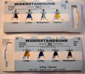
The color codes are quite easy to learn by memory but sometimes it is difficult to see if a ring is yellow or orange (sometimes green and blue can be difficult). So always good to have a DMM to check values (as you do). Also which way to "turn" the resistor can be difficult to know so you read from the correct side. It depends of how precise the rings are "painted".
Once again, you all provide wonderful advice and tips that I've been scouring the web for. I am willing to learn and do the work. I am loving learning more about it all. However, the things that you've learned through years of experience and/or that helped you get over "the hump" and build confidence when you too were a noob are very much appreciated. I've learned enough things "the hard way". It's actually encouraging to hear that veteran builders make mistakes, too. I was reading the PSU summary that AndrewT collaborated on that 6L6 linked to (I think) - It was EXTREMELY valuable to a person with my lack of experience, and I'd have never found it. Bulb tester on the list to build and a variac to buy.
Part of my challenge is relatively poor vision. I build under a 2.5x fairly large magnifying light AND use a pair of 3.5x "jeweler's glasses" stacked on top of my readers on occasion for smaller close-up work like SMD. 0805 parts are my hard limit. 0603 and smaller is dust to me. I inspect joints (solder joints, you deviants) with the 10x loupe over the jeweler's glasses. Yep, I don't see very well. I'm an old(ish) noob.
On the to do list -
Start new thread ... something like "a Newbie's M2x journey"
Post rest of ramblings and future pictures there and leave this thread tidy for specific questions.
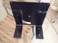
Elwood625,
Can you post a pic (front view) showing how you mounted the L-bracket for the toroid doughnut + steel enclosure. That's a pretty heavy toroid and particularly heavy with the steel enclosure!
Edit...or perhaps you are just mounting it to the future front panel, doh!
Thanks,
Anand.
Can you post a pic (front view) showing how you mounted the L-bracket for the toroid doughnut + steel enclosure. That's a pretty heavy toroid and particularly heavy with the steel enclosure!
Edit...or perhaps you are just mounting it to the future front panel, doh!
Thanks,
Anand.
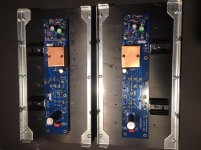
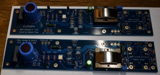
Now I am one step further. Components mounted on both amp PCBs. Edcors shielded first with 3M copper tape like they show on Edcor web:
EDCOR - MXcs Series
….and then a layer of mu-metal shield. This way I get a shield also on backside of Edcor. I assume this will be enough shielding. If not I can always build a mu-metal box and put on as cover.
I mounted C0 (220 pF). You can also see the "alien" 39,2k which is not Vishay Dale.....but only Vishay…...which should have been 37k!!
Next step is assembling the HiFi2000 5U Deluxe mono block chassis and built the PSUs (have 2 x 500 VA trafoes and L-brackets for it.....and also a magnetic steel-shield around them. Also the steel rondel is a speciel steel that act as a magnetic shield). As boxes are made for stereo amp I have much room to place trafo far away from amp board. HiFi2000 made special mono back panel still with cut outs so DiyAudio Store special kit fits.
Attachments
Elwood625,
Can you post a pic (front view) showing how you mounted the L-bracket for the toroid doughnut + steel enclosure. That's a pretty heavy toroid and particularly heavy with the steel enclosure!
Edit...or perhaps you are just mounting it to the future front panel, doh!
Thanks,
Anand.
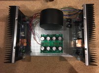
I had to build something similar on mine
Attachments
I found that using a steel case around an Antek AS-4218 worked well for my M2x. I also positioned the main channel boards toward the rear of the 400mm deep chassis, which gave some extra physical separation. The Antek AS series toroids have both electrostatic shielding and a magnetic shield band around the outside, so that certainly helps as well. My M2x is so quiet that I need to pay more attention to how I route the interconnects from my preamp.
Meper, looks like you did a fine job wrapping the shielding tape around your Edcors. I was cautious about breaking the tiny wires, so I left mine alone.
Meper, looks like you did a fine job wrapping the shielding tape around your Edcors. I was cautious about breaking the tiny wires, so I left mine alone.
@TungstenAudio
Great insight - thank you! Not completely relevant for this build, but for a moment I was pondering "go big or go home" with the AS-6218 for no good reason at all other than the newcomer attitude of bigger must be better.
The real question - do you have any insight why Antek does not have cases for anything larger than the 400VA? I read the specs to the best of my knowledge, and I can't see why a larger transformer would not require equal shielding, but they're not offered. It's a bit off topic, but it will satisfy my curiosity. I was also looking larger b/c the cases for the 400VA are out of stock, and I was seeking instant gratification...
Looking at the AnTek Products website, I don't see any AS series transformers larger than 400VA. That means that the 500VA and 600VA toroids that some use are unshielded. It seems that AnTek intends their larger transformers to be primarily used for industrial applications rather than audio. I successfully used an AN-6450 for a Hafler DH-220 build several years ago, but that used a special power supply consisting of about 11,000 uF followed by a cap multiplier, followed by 18,000 uF on each rail for each channel.
I think the 400VA toroids are a good size for the FirstWatt clones. The one I'm using in my M2x exhibits the rated 18 VAC at the inputs of the discrete rectifier bridges, and I'm getting +/– 22.6 VDC on the main channel boards. I'm also currently preparing the chassis for an Aleph J that will have a pair of 300VA AS-3220 toroids in a dual mono configuration. I plan to run the Aleph J just as hot as the chassis will allow. I've skipped the steel cases for those transformers for now, but have left room for them if they become necessary.
I think the 400VA toroids are a good size for the FirstWatt clones. The one I'm using in my M2x exhibits the rated 18 VAC at the inputs of the discrete rectifier bridges, and I'm getting +/– 22.6 VDC on the main channel boards. I'm also currently preparing the chassis for an Aleph J that will have a pair of 300VA AS-3220 toroids in a dual mono configuration. I plan to run the Aleph J just as hot as the chassis will allow. I've skipped the steel cases for those transformers for now, but have left room for them if they become necessary.
- Home
- Amplifiers
- Pass Labs
- The diyAudio First Watt M2x