M2X experience
Hello M2X-builders,
today I put out the NORWOOD-boards for a second inspection.
I checked the orientation of the OPAmp / BufferAmp, You can see on the
foto that the points at PIN1 of each OPAmp correspond with the points on the
pcb (U4 and U5).
I checked the Diodes orientation: D1 and D2 can't be turned around (3 pins) or
would not fit; upsidedown - impossible, pins would be in the air.
D3 and D4 Kathodeline on the part corresponds with the line and 'K' on the
board.
I also checked the resistors. Am I blinded? 😕
Greets Dirk
Attachments
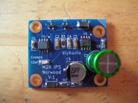
Cubicincher, I looked at your photo and it doesn't seem to show any obvious errors. Both zener diodes are oriented correctly. The two SOIC-8 integrated circuits are oriented correctly and they aren't swapped. The electrolytic capacitor is oriented correctly.
I find that hand-soldered SMD boards usually have "open circuit" faults more often than any other kind of mistake. You attempted to solder pin N onto landing pad P however a connection was not made -- it is an unintentional open circuit.
One way to check for this is to use a Digital Volt Meter on ContinuityTest ("buzzer") mode. Probe only the metal legs of electronic components -- don't probe the solder or the PCB traces. If the metal leg of U4 pin 2, shows continuity to the metal leg of U5 pin 8, then you can be certain that both chips are correctly soldered to the PCB and there is not an open circuit anywhere in that current path. Continue this way for the rest of the board. I myself just built 30 Norwood boards by hand, and buzzed out every trace on every board. Once you get proficient it only takes 5 minutes per board. For you, not yet proficient, it will take 10 minutes. So what, no problem, you've got 10 minutes.
Finally, if you give up completely, I will test and repair Norwood boards for free, but YOU pay the cost of postage in both directions. The US-to-Europe postage costs USD 15, I have no idea what the Europe-to-US postage costs. Norwood and only Norwood.
Can also see from the star washer marks that there has been electrical contact to the main board. Is a star washer mandatory to make electrical contact? ….is it possible to avoid marks....and still have good electrical contact?
Was same "error" on both boards?
Was same "error" on both boards?
Dirk,
Assuming no errors on the PCB,
The next question is "did you make a wiring error in the daughter card selector switch?"
Could you place Norwood in a position currently occupied by Austin or Mountain View? It may be a safe assumption to say that either of those positions work properly.
Assuming no errors on the PCB,
The next question is "did you make a wiring error in the daughter card selector switch?"
Could you place Norwood in a position currently occupied by Austin or Mountain View? It may be a safe assumption to say that either of those positions work properly.
M2X experience
Thanks Mark Johnson, 6L6 for your help!
I don't give up! 😀
I will measure through the boards tomorrow again. I have this phenomena
on both boards (left and right channel).
Then I put in the Tucson - boards today. Same runaway of offset.
I measured from the standoffs (switcherboard) to the mainboard
and did not find that there is no contact or any wires crossed.
Then I thought: Could this be affected by the length of the cables from
switcher board to the mainboard. I read a lot, that OPAmps can be sensitive
to bad routing of pcb traces or
in my case - long cables? perhaps?
I will find the reason.
But the M2X is playing music for some hours now (with the two other boards)
I am driving it this evening with my Pass Aleph P1.7 clone. Also very nice
combi.
And it sounds goooood!
Have a nice weekend!
Dirk
Same "run away" using two different input boards on both channels. Then my logic tells me that error is not on the input boards. I would try to mount one of these input boards directly on main board to eliminate the switch arrangement.
answer to MEPER
I fully agree with you MEPER. Logical conclusion.
That is why I thought of the length of the cables (main pcb to switcher/ inputboards) influencing anything.
But today I resolder the Norwood - board. I found 1 pin at the buffer-OPAmp
(and measured it) that seems to be suspicious.
I am cooking amplifiers - and I will never give up since the 'meal is served'! 😀
Thanks for your help!
Greetings from Dirk
About chassis for M2X:
The predrilled holes in the heatsinks for Dissipante has been done for DiyStore only?
Has some pictures of M2X made as mono blocks?
I am looking for a chassis like the 1. version of ACA (mono block version) just a bit larger and then "mirrored" of course 🙂
It seems that HiFi 2000 shop don't sell such chassis.....
One option is to buy a stereo Dissipante with the predrilled holes for MX2 boards and then bild the rest as DIY. I build external PSU so I don't need space for the PSU inside the cabinet(s).
Re-soldering pin 1 of a chip on a Norwood board, is not expected to correct the problem mentioned here:
Then I put in the Tucson - boards today. Same runaway of offset.
answer to Mark Johnson
I fully agree with you. If you have the same situation with two TUCSON boards and two NORWOOD boards and the same on the left and the right channel than something is fishy anywhere else. 🙄
It's my turn....
Cheers
Dirk
I fully agree with you. If you have the same situation with two TUCSON boards and two NORWOOD boards and the same on the left and the right channel than something is fishy anywhere else. 🙄
It's my turn....
Cheers
Dirk
@Meper, #1349:
Modushop is selling the pre-drilled chassis that are available in the DiyA Store also directly:
DiyAudio products
For us in Europe that is a bit easier to get - just received a 5U400 Deluxe chassis this week 😉
Best regards, Claas
Modushop is selling the pre-drilled chassis that are available in the DiyA Store also directly:
DiyAudio products
For us in Europe that is a bit easier to get - just received a 5U400 Deluxe chassis this week 😉
Best regards, Claas
OK....I must believe that it also has the holes in the heatsinks for mounting the M2X PCB. It seems not specified?
Who has specified the predrilled holes size and placement? ….DiyAudio team?
What do you use a 5U400 for?
A 4U300 should be sufficient for M2X. You just want to be on the safe side or have very tall E-caps for the Power supply?
Who has specified the predrilled holes size and placement? ….DiyAudio team?
What do you use a 5U400 for?
A 4U300 should be sufficient for M2X. You just want to be on the safe side or have very tall E-caps for the Power supply?
Here is the mounting info..
Universal Mounting Specification – diyAudio Store
For us i europe ordering direct from Modu, look at the goods under the "Diy Audio Products". In the discription of a amp chassis i says "You can read all the mechanicals specs here." "Here" is a link to DiyAudio.
Universal Mounting Specification – diyAudio Store
For us i europe ordering direct from Modu, look at the goods under the "Diy Audio Products". In the discription of a amp chassis i says "You can read all the mechanicals specs here." "Here" is a link to DiyAudio.
Thank you…..there was the Mounting Specification.
Direct from Modu…...I have looked at the mechanicals specs…..but did not find the UNS like in the diyAudio Store from your link. But it may be there…..
What I also has a doubt about is if the back panel connectors are included (RCA, IEC, etc.) They show it on the picture but does not specify it.....and does not show it as a special extra option. So I guess this package is sold by Diy Audio Store only as a kit?
Yes, the rear panel kit. Very nice, very nice brass stand offs, you can see them used in 6l6's build guide for the BA3 amplifier. If you don't get the deluxe box from the diy store, make sure you specify the pre cut rear panel and UMS predrilled heatsinks.
Also, I would strongly suggest the floor pan, tons of predrilled holes not only for ventilation, but for all your screw mounted boards, transformers, etc. Plus, does wonders to stiffen the chassis and avoid drilling through bottom cover for a much neater appearance.
You can also route wiring underneath to help with hum avoidance. Wiring will be between the panel and bottom cover. Good place for wiring from transformer and such.
Russellc
Last edited:
The Deluxe 5U400 directly from ModuShop does not include a back panel kit. It has, however, all necessary cutouts in the back panel, all UMS threaded holes in the heatsinks, and the extra threaded holes in the silver front panel.
It also comes with the extra bottom pan mentioned by Russellc in the previous post.
You can also get a black front panel if you ask them, but that one only without the extra threaded holes the silver panel has.
Note that the IEC cutout in the back panel is a tall one, so only IEC inlets with fuse and switch combined will fit.
I will use my case to build a universal amp case. 400 to have space for big dual mono power supplies, 5U for having enough heatsinking for future projects.
First inhabitant will be a SissySIT ... 🙂
Best regards, Claas
Last edited:
Yes, the extra bottom with the 10 x 10 mm holes is very nice and is mandatory if a big power supply is built. The special connector kit I will get from the DiyStore. Will see what I find out regarding external or internal PSU for the M2X. I want to avoid hum pick up from the PSU. Seems the Edcor's is a little sensitive regarding this.
The SissySIT is not "that" sissy…..if it requires a 5U ? 🙂
The SissySIT is not "that" sissy…..if it requires a 5U ? 🙂
Just wanted to let folks know that the GB for the Melbourne Preamp daughterboard for the M2X will be closing in a few days if you want to get your order in.
Also of note, JPS64 is designing a new Preamp motherboard to allow two of these daughterboards to be used as an integrated stand-alone preamp. Will have linear dual trafo PSU with a Mark Johnson BJT cap Mx on board.
Also of note, JPS64 is designing a new Preamp motherboard to allow two of these daughterboards to be used as an integrated stand-alone preamp. Will have linear dual trafo PSU with a Mark Johnson BJT cap Mx on board.
Here is the mounting info..
Universal Mounting Specification – diyAudio Store
For us i europe ordering direct from Modu, look at the goods under the "Diy Audio Products".
Yes the M2x main amplifier boards conform to the UMS, the first time this was asked here seems to be post #98 and the first time it was answered was post #99.
As the photos in the Store show, M2x's main ampllifier board has four columns of mounting holes arranged in two rows. The columns are on a center-to-center pitch of 80mm and the rows are on a center-to-center pitch of 40mm, as UMS requires. The outside edges of the board extend beyond the centers of the drill-holes, for mechanical stability and strength.
A member measured the dimensions of the main board and posted their numbers here, some time within the last 3-5 weeks. Or you could just measure the boards that the Store ships you 🙂
- Home
- Amplifiers
- Pass Labs
- The diyAudio First Watt M2x