DVM on continuity-buzzer mode is your best friend when assembling SMD boards. Touch the probes upon component pins (not PCB traces) to check whether you've got unwanted open-circuits and short-circuits. In my experience, I discover opens a lot more often than shorts, when probing just-soldered SMD boards.
Oooooo thank you. I'll definitely use that.
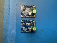
Made it through Norwood successfully but I still have a preamp board that was my first attempt at SMD and didnt end so well. Open to all pointers I can get!
Made it through Norwood successfully but I still have a preamp board that was my first attempt at SMD and didnt end so well. Open to all pointers I can get!
Mark, 6L6, Nelson and community... thanks for all your contribution to making this M2x come to life.
It sounds amazingly solid, clean and depending on buffer, smooth as silk or transparent and defined. I've built the F5, F6, now the M2x. This is the one I'm staying with. It's next level, as the kids say.
I've built out the Ishikawa, sounds as I would expect, from a Nelson Pass design front end, smooth. Put together the Austin, which is the one I'm staying with for now. It sounds clean, clear, no muddy bass or ringing highs - really like the music it makes. I'm with for the boards for the Milpitas, and have parts for the Norwood.
Pausing briefly from building, had a total knee replacement on Friday, so listening is about all I can do right now. Tinkering is on hold.
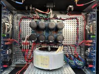
Here's pics of the main board ready to make some music.
All the sharing, wisdom and insight shared on these forms has been invaluable to me in building this and many other projects. Thanks to all who have shared.
Carl
It sounds amazingly solid, clean and depending on buffer, smooth as silk or transparent and defined. I've built the F5, F6, now the M2x. This is the one I'm staying with. It's next level, as the kids say.
I've built out the Ishikawa, sounds as I would expect, from a Nelson Pass design front end, smooth. Put together the Austin, which is the one I'm staying with for now. It sounds clean, clear, no muddy bass or ringing highs - really like the music it makes. I'm with for the boards for the Milpitas, and have parts for the Norwood.
Pausing briefly from building, had a total knee replacement on Friday, so listening is about all I can do right now. Tinkering is on hold.
Here's pics of the main board ready to make some music.
All the sharing, wisdom and insight shared on these forms has been invaluable to me in building this and many other projects. Thanks to all who have shared.
Carl
Attachments


You’ll notice that all of Mark Johnson’s designed boards starting from Ishikawa all the way up to IPS9 (Milpitas) have 4 bolts/hole designations: Vcc (pin 3), Vee (pin 1), analog signal input (pin 2) and analog signal output (pin 4). What is missing is ground. Without a designation for a definite ground, the ability to create ‘gain’ becomes rather challenging. One diyaudio member, xrk971 has several boards that provide gain, all sold on his etsy website (they also have a separate ground lead that needs to be connected 😉) . One example is here. Of course, any assistance with building that board or any of his boards should be directed to the respective threads.Possible to give a bit of gain to the IP9 board to avoid using the transformer for gain?
The M2 (and M2x) are unique because the actual single active gain stage is completed by an autoformer for voltage gain. The front end is a buffer, and the back end are a pair of Mosfets in push pull source follower configuration (0dB in voltage gain, but not current gain) biased in Class A.
The answer is basically…No! MJ’s current input buffer designs all have 0 dB gain and will remain that way.
But an intrepid diy’er is free to design a new daughter board for voltage gain and that experimentation is welcomed and encouraged. Post #56 has a drawing to assist you in where the hole designations should be (for compatibility with the M2X) as well as board dimensions.
Best,
Anand.
Last edited:
But an intrepid diy’er is free to design a new daughter board for voltage gain and that experimentation is welcomed and encouraged. Post #56 has a drawing to assist you in where the hole designations should be (for compatibility with the M2X) as well as board dimensions.
The circuit schematics of all nine M2x IPS cards are in the public domain; nobody owns them because everybody owns them. Nobody "controls" them. So you can use them however you wish; make tiny modifications if you want. Make enormous modifications if you wish. Do with them as you see fit. If you decide to modify Milpitas and add a fifth bolt hole, to bring "ground" onto the card, so you can easily adjust the gain above or below 0dB -- go right ahead! Nobody can stop you, and truthfully: nobody will even try to stop you. Not Anand, not Nelson Pass, not me, not 6L6, and not Jason Donald. Use and abuse all nine IPS circuits however the spirit moves you. diyAudio is a hobby; do it your way and have fun.
Ooooooohhhhhhh...and have parts for the Norwood.
I would strongly suggest building that.
😎
Yes.Possible to give a bit of gain to the IP9 board to avoid using the transformer for gain?
However, the transformer is what gives M2x it's incredible and delightful character.
I also think that the most important part of the M2x that gives it its sound character is the Edcore transformer.
For this reason I plan to replace it with an amorphous core type made by Ivan Bisesik.
For this reason I plan to replace it with an amorphous core type made by Ivan Bisesik.
What rails should we expect for the Toshiba Jfet version? A diyer has asked management what
Idss is preferred there.
Idss is preferred there.
The M2x input stage card called "Ishikawa", which is included in every set of M2x boards sold by the diyAudio Store, is a direct and slavish copy of the First Watt M2's input circuitry, as exhibited in the Official M2 Schematic (link) posted in October 2015. Because the First Watt M2 used ±23 volt DC supply rails, the M2x does too. And so does M2x's input card named Ishikawa. Similarly, the First Watt M2 uses Toshiba K170/J74 JFETs, and M2x Ishikawa does too.
I've attached an annotated schematic diagram below. Hope that's what you mean by "Toshiba JFET version".
_
I've attached an annotated schematic diagram below. Hope that's what you mean by "Toshiba JFET version".
_
Attachments

Cedarburg boards are stuffed, minus Q1, which was backordered at both Mouser and Digikey. They should be arriving in about a week. As I post these photos, I notice I have one R3 "backwards." Will OCD force me to swap it?


A question which is more to further my understanding as much as anything.....would substituting the 11v zener diodes on IPS9 Milpitas, with 10v zeners be OK?
I looked up the DS of the 2 op amps and both are within their limits if provided with another 2v, assuming the 23v rail input from the main amp PSU .
I 'assumed' this is OK, but I also am fully aware there would be a very good reason that Mark chose 11v zeners and not 10v!
I looked up the DS of the 2 op amps and both are within their limits if provided with another 2v, assuming the 23v rail input from the main amp PSU .
I 'assumed' this is OK, but I also am fully aware there would be a very good reason that Mark chose 11v zeners and not 10v!
Choosing the Zener diodes for Milpitas is an exercise in making assumptions and then juggling them.
- What are the min and max power supply voltages that your Milpitas will ever see on its I/O bolts?
- What is the maximum peak-to-trough sinewave voltage (undistorted) that you insist your Milpitas MUST produce (driving Edcor primary)?
- Since neither chip in Milpitas is Rail-To-Rail, what is the minimum required supply voltage at the opamp power pins, to give the required max sinewave?
- After looking at the datasheets, what is the maximum supply voltage at the opamp pins that you'll allow (including your own personal margin-of-safety)?
- What tolerance will you specify for your Zener diodes?
Norwood finished and installed last evening. Played 2 hours of music, 6 hours today and Wow... I was using the Austin and liked to overall sound presences, the attack and release of the notes and clarity. With the Norwood that has all been blown away and become many times better and more everything. It's like all the instrument and voices are coming out of the speaker into the room with you. No lag, just music. Amazing. Milpitas is in the building queue and next up.
Have encountered a challenge I need some helpfuil input on. Each time I take an IPS off the screws washer and spacer nut loosen and Ive had to take the board off the heat sink and tighten everything from the bottom.
Am I tighten the top module to tight, yes subjective question?
Is this typical?
Will something like thread locker help?
I'm also worried that I'm goin to crack the main board by over tightening the cards.
Thank for the help.
Carl
Attachments
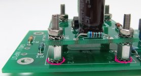
Secure the cards exactly as shown.
(Which is to say, use all of the star washers, in the prescribed locations. Yes, it's a lot of them, but the point is for it to be secure with minimal stresses and without excessive torque.))
…and yes, Norwood is amazingly good. It’s always been my clear favorite.

(Which is to say, use all of the star washers, in the prescribed locations. Yes, it's a lot of them, but the point is for it to be secure with minimal stresses and without excessive torque.))
…and yes, Norwood is amazingly good. It’s always been my clear favorite.
Last edited:
After the bolts and the first set of hex threaded spacers are installed, you could think about applying some liquid adhesive or paint, whose purpose is to seal the spacers to the motherboard. If you like pink nail polish for example, here's an idea. On the other hand you might have a royal pain in the axx if, some day in the future, you decide to disassemble the motherboard and remove the polish.
_
_
Attachments

- Home
- Amplifiers
- Pass Labs
- The diyAudio First Watt M2x