The amplifier pictured below has been my experimental platform for the past few years. You would get a laugh if I added a pic of the bottom plate...looks like it was used for target practice. Currently installed are the Toriody trans w/ 22V secondaries, H9KPXG on-off/soft start/relay, SLB PSU (in place of the Universal board), M2X circuit boards (formerly an F4, M2, and then Aleph J), and Ready-to-Run SSR speaker protection.... how many volts on a +/- power inputs does it take to "activate" the M2 circuit?
So to answer my own question, here's what happens at various settings while bringing the voltage up slowly. I would stop for a bit at each of the settings (maybe 1 to 5 min.) and make some notes.
*10% on Variac - Nothing, there isn't enough power to trip the relay on the H9KPXG, only the "OFF" LED will light up at this point.
*20% - Relay now closes, and powers up the SLB PSU lighting it's LED's, but no readings on either source resistors, or outputs (offset).
*30% - Starting to read some voltage on the source resistors, offset is wonky but steady.
*40%-50% - Source resistor voltage increasing but no AC output when given a smallish (500mV) input.
*60% - Starting to produce a AC output (nice sine wave on scope) given an AC input.
From there I went straight to 100% and adjusted offset to ~0.
Connecting it to speakers and source produces nice sounding music, but also a bit of hum with ear close to the speaker. Ugh, now I have to chase down that hum. Funny thing is there was no hum (dead quite) with the Aleph J boards installed. Any ideas on the hum...all are welcome.
Currently there is no shielding on the M2X transformers, I'll try that first and report back.
Lot's of porn for ZM...


Kevin,
First of all, excellent build. I really like how you vertically mounted your Toroidy. I have never done that with any of mine so that definitely looks cool and serves the purpose of keeping the toroid far and away from sensitive circuitry.
Thanks for the info on what point the source resistors (and hence Mosfets) start conducting depending on the AC line voltage. That’s useful.
The interesting thing is I have a similar setup to yours including the large well shielded and encapsulated Toroidy. So I am praying I don’t have hum since as you have pointed out, the Edcor transformer is unshielded in stock form. I think you are on the right track to making a mu metal enclosure for the transformer, there are countless examples on this thread. I just put a mu metal wrap on mine.
Suggestions for chasing down the hum (you’ve probably already addressed these and thought of them):
-Consider tightly twisting and braiding the AC wires from your Toroidy, both the primary and secondaries, and shortening them. Make sure they are far and away from the main amplifier boards, particularly the Edcor unit and definitely the input stage area.
-This would also mean that your rectified DC wires need to be far away from the AC wires from your Toroidy transformer. Twisting your DC wires is an option as well.
-I seem to recall there were individual right and left main boards for this design so swapping them might help in minimizing the length of the input wiring?
- At the same time, suggest swapping your Toroidy to the opposite side, if you know what I mean. I’ve seen more examples of fellas mounting it vertically towards the front panel.
-If you have a true RMS voltmeter, you should be able to measure what your AC hum is on the speaker outputs, although I prefer a scope and/or my HP3478 (a bench meter with 100khz bandwidth). Don’t know what tools you have. I try to aim for 1mV RMS max for solid state amplifiers (if possible!).
Those are my suggestions but I’m sure there are other varieties one can try.
Good luck, I’m sure you’ll do fine!
Best,
Anand.

Kevin,
Regarding hum... many have suggested that speaker ground be connected directly to power supply ground to reduce hum. That made a significant difference in my build.
Just a thought.
Carl
Regarding hum... many have suggested that speaker ground be connected directly to power supply ground to reduce hum. That made a significant difference in my build.
Just a thought.
Carl
Oh, I have all the tools...I just don't use them very well.If you have a true RMS voltmeter, you should be able to measure what your AC hum is on the speaker outputs, although I prefer a scope and/or my HP3478 (a bench meter with 100khz bandwidth). Don’t know what tools you have. I try to aim for 1mV RMS max for solid state amplifiers (if possible!).
I’m trying to learn how to measure ripple and noise on the DC power supply, and noise at the amplifier outputs. As I make modifications (twisting and shortening wires, shielding transformers, etc.) I’d like to know if I can “see” the difference before listening to it. I’ve been watching videos and reading papers. While I’ve learned a bunch, I haven’t found anything showing exactly how to measure the noise on an audio amplifier output. If anyone would care to help, or put me in the right direction it would be greatly appreciated.
^ Not sure what equipment you have on hand, but... almost without a doubt, the best thing I did was learn to use a pair of cheap earbuds (of course be careful) connected to the speaker outs with inputs both shorted and not shorted while moving things around and twisting etc. Of course that's over-simplified, but ... Someone around these parts had an attenuator / PCB specifically for that if I'm not mistaken... I truly don't remember, but if someone sees this they may be able to point you in the right direction.
As for an "easy" way...
https://quantasylum.com/products/qa403-audio-analyzer
Certainly not a budget way... and it's not the world's lowest noise floor, but it sure does make it easier for someone like me that's trying to learn.
As for an "easy" way...
https://quantasylum.com/products/qa403-audio-analyzer
Certainly not a budget way... and it's not the world's lowest noise floor, but it sure does make it easier for someone like me that's trying to learn.
Shame on you for tempting me to buy yet another toy...Bad, Bad, Bad.As for an "easy" way...
At this point I have an O-Scope, Differential Probe, Bench & 2 handheld meters, Signal Generator, Autoranger/Sound Card/Spectrum Analyzer (software on PC), Bench Top PSU, Dummy Load, Variac, DBT, MEGA 328, and maybe some stuff I can't remember. Still learning how to use most of it...Not sure what equipment you have on hand...
While no solution to measuring noise, I wonder if a simple inductive amplifier would be helpful in locating the root of hum or buzz. I'll pull out my toner and probe the next time I fire up a channel just out of curiosity, but maybe someone more knowledgeable can offer some input.
Depending on the sound card ... that might be enough. I haven't tried it with an internal sound card on a PC, but I believe I've seen it done. I've done noise measurements with REW + Focusrite. X and the group over in the "REW thread" are incredibly helpful.At this point I have an O-Scope, Differential Probe, Bench & 2 handheld meters, Signal Generator, Autoranger/Sound Card/Spectrum Analyzer (software on PC), Bench Top PSU, Dummy Load, Variac, DBT, MEGA 328, and maybe some stuff I can't remember. Still learning how to use most of it...
Basically, you're (with proper wiring) just hooking up the outputs of the amp with no signal to the 'tester' and checking the output. People do certain weightings through software, but you'll pretty quickly see what the frequency of the hum / noise might be if there is a predominant one present and it's level relative to a known point and/or if you calibrate it to a known voltage.
Just to tempt you... this takes <1 minute to do with the QA... My Aleph 60 noise. A-weighted.

Still learning a bit how to set up properly each time, measure it the same way each time, and digest it all, but ... look at the pretty colors!

With an oscilloscope you can start by checking the power supply ripple and the amplifier output noise.
The power supply with capacitance multiplier should have less than 5mV ripple but that should be measured to hopefully eliminate it as a source of the noise. To check for ripple connect the probe ground to PS ground and probe to PS V+ and check for ripple voltage. Repeat for V-.
If that checks out, then make sure the amplifier input is shorted, attach an 8 Ohm load to the speaker output of one channel, probe ground to load ground, probe to load positive, and check for output noise.
There is a lot of information and instructions on the web on measuring noise using an oscilloscope.
Post the oscilloscope screen shots for review.
Amplifier noise can be difficult to assess without measurements since people have speakers of various sensitivity. A person may hear no noise from low sensitivity speakers but have a noisy amplifier. Their amplifier may have many construction issues but they are sure that their amplifier was built to the highest standard, and that details such as grounding, layout, twisted wires, etc. are not important since they do not hear any noise. Conversely a person may hear a bit of noise from high sensitivity speakers, and the amplifier was constructed with proper detailing for low noise but it may have a level of noise that is appropriate for its type. Or an amplifier may be very quiet and no noise is heard from all speakers.
The M2X with its unshielded voltage gain transformer is the noisiest of all First Watt type amplifiers. So noise may be audible if your speakers are very sensitive. The FW M2 Specifications specify a noise level of 500uV.
O-scope settings: AC coupling, BW Limit ON, 1X probe. Vrms measurement jumps around anywhere from 1.7 to 3.8mVTo check for ripple connect the probe ground to PS ground and probe to PS V+ and check for ripple voltage. Repeat for V-.
Post the oscilloscope screen shots for review.
Attachments
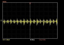
8mV ripple is not bad. As for the frequency, if the horizontal axis is 50us per division, then the period is approximately 40us, and frequency is 1/0.000040s=25 kHz.
Try changing the time base so that the horizontal time is more than 50us per division. For instance, 60Hz period is 16.666ms. So you want something in that neighbourhood, perhaps 20ms per division. Or 10ms or even 5ms per division.
Did you measure the amplifier audio output?
Try changing the time base so that the horizontal time is more than 50us per division. For instance, 60Hz period is 16.666ms. So you want something in that neighbourhood, perhaps 20ms per division. Or 10ms or even 5ms per division.
Did you measure the amplifier audio output?
Last edited:
No, I should have before I tore it apart to get at the PSU more easily (and safely). My plan is measure audio output shielding ONE board with a steel box wrapped in MU metal and compare it against the other channel with NO shielding.Did you measure the amplifier audio output?


Last edited:


Similar to what a regulator would require, the SLB capacitance multipliers will benefit from bulk storage capacitance on their output. At least 10,000 uF, and 36,000 uF better still. This is covered in Nelson's article on regulators. I have found the difference to be noticeable.
The spikes are at 120Hz but the ripple is low. Generally ripple is lower when the current is low and higher when the current is high. I assume the power supply was not connected to the audio boards.
There is also a background of high frequency noise at a low voltage.
The questions of the spikes and high frequency noise are probably best asked on the SLB thread and perhaps xrk971 can provide answers:https://www.diyaudio.com/community/...ct-crc-cap-mx-class-a-power-supply-gb.336479/
There is also a background of high frequency noise at a low voltage.
The questions of the spikes and high frequency noise are probably best asked on the SLB thread and perhaps xrk971 can provide answers:https://www.diyaudio.com/community/...ct-crc-cap-mx-class-a-power-supply-gb.336479/
Use case for M2X for LF slot open baffle via LX Mini, Sissysit 42 for mids/highs. M2X was noisy so swapped it out for Aleph J.With an oscilloscope you can start by checking the power supply ripple and the amplifier output noise.
The power supply with capacitance multiplier should have less than 5mV ripple but that should be measured to hopefully eliminate it as a source of the noise. To check for ripple connect the probe ground to PS ground and probe to PS V+ and check for ripple voltage. Repeat for V-.
If that checks out, then make sure the amplifier input is shorted, attach an 8 Ohm load to the speaker output of one channel, probe ground to load ground, probe to load positive, and check for output noise.
There is a lot of information and instructions on the web on measuring noise using an oscilloscope.
Post the oscilloscope screen shots for review.
Amplifier noise can be difficult to assess without measurements since people have speakers of various sensitivity. A person may hear no noise from low sensitivity speakers but have a noisy amplifier. Their amplifier may have many construction issues but they are sure that their amplifier was built to the highest standard, and that details such as grounding, layout, twisted wires, etc. are not important since they do not hear any noise. Conversely a person may hear a bit of noise from high sensitivity speakers, and the amplifier was constructed with proper detailing for low noise but it may have a level of noise that is appropriate for its type. Or an amplifier may be very quiet and no noise is heard from all speakers.
The M2X with its unshielded voltage gain transformer is the noisiest of all First Watt type amplifiers. So noise may be audible if your speakers are very sensitive. The FW M2 Specifications specify a noise level of 500uV.
Bugged me about not being able to use the M2X so opened the case and checked wiring per the many hum, buzz threads and QA hints.
In the Sissy, I independently grounded the purple Antek shield to chassis and its quiet. In the M2x I had mounted the purple shield ground to the star point connected to the IEC inlet and PS ground. I hooked up the M2X with small sensitive speakers and the buzz present on both channels. Disconnected the purple to the star ground and independently grounded it to chassis floor adjacent to the 4218.
Big difference, much quieter. Put the M2x back in to the main system. Minor but tolerable hum on the LF, but progess nonetheless.
https://www.diyaudio.com/community/threads/antek-toroid-grounding.253914/post-3876291
Yes there is! Figuring out how to measure noise is turning out to be more of a challenge for me than expected. I'm learning to use the oscilloscope and spectrum analyzer in ways I hadn't imagined. Both are powerful tools and it would appear I've just barely scratched the surface of their capabilities.There is a lot of information and instructions on the web on measuring noise using an oscilloscope.
As far as the M2x is concerned, with the next iteration in this chassis I'm going to take many of the suggestions above, and what I've learned recently in the Aleph J thread, and incorporate them into my changes. I'll be going back to basics, with most of the parts being on hand anyway. I'll be (re)installing the following: Antek AS4218( moving it to the front of the chassis), Universal PSU form the store using a basic bridge rectifier blocks, turning the amp boards around on the heatsinks as intended (for shorter input connection), removing speaker protection. and twisting all wires appropriately. All that in conjunction with the isolation boxes over board mounted transformers...we'll see what happens.
Now with the mains transformer being in the front of the amplifier, does anyone have suggestions for shielding the AC wire going through the chassis from the switch/fuse holder on the back panel to the transformer up front? or isn't this an issue?
Regarding the AC wire from the rear panel up to the front mounted transformer, maybe a clamp-on ferrite could help if you can find one. I have also used wide copper tape to shield the twisted wires. I already use copper tape to shield the pickup cavities in my bass guitars, so I have a roll on hand. Seems to help.
I locate the thermistor pair and line rated 47nF cap next to the transformer. I also tie the transformer ground wire (purple on the Anteks) to the chassis next to the transformer, usually using one of the mounting screws for the thermistor terminal wiring strip.
I locate the thermistor pair and line rated 47nF cap next to the transformer. I also tie the transformer ground wire (purple on the Anteks) to the chassis next to the transformer, usually using one of the mounting screws for the thermistor terminal wiring strip.
- Home
- Amplifiers
- Pass Labs
- The diyAudio First Watt M2x