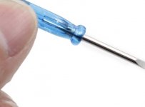
Since IPS7 intentionally and deliberately puts the DIP8 sockets at the outer perimeter of the PCB, you have an unobstructed path to use a flat bladed screwdriver as a "wedge"; to gradually lift a chip out of its socket. Gently rocking up and down.
You can use the screwdriver as a temporary & interim workaround, while you wait for Jameco to deliver your Truly Important IPS7 Ownership Tools
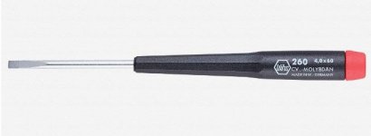
Here is success-with-IPS7 tool #1
Here is success-with-IPS7 tool #2
I purchased these Jameco products, and sent them to the original Listening Reviewers of IPS6 and IPS7. I wanted to be certain they had everything they need, to perform whatever experiments they could devise. The reviewers seemed quite pleased with the gift.
_
You can use the screwdriver as a temporary & interim workaround, while you wait for Jameco to deliver your Truly Important IPS7 Ownership Tools
Here is success-with-IPS7 tool #1
Here is success-with-IPS7 tool #2
I purchased these Jameco products, and sent them to the original Listening Reviewers of IPS6 and IPS7. I wanted to be certain they had everything they need, to perform whatever experiments they could devise. The reviewers seemed quite pleased with the gift.
_
Attachments
New circuits to play around with, and free tools for fearless amp builders - good on ya Mark Johnson! 🙂
The trick is to pull the opamp out of the socket 100% horisontal without one end flipping up first which will bend the pins.....and maybe a pin stuck in a finger which does not feel very nice.
Even the expensive sockets with round holes tend to be a bit looser when an opamp has been inserted a few times. So it will be easier to insert and pull out but connection will not be as good as first time an opamp is inserted in a brand new socket.
Even the expensive sockets with round holes tend to be a bit looser when an opamp has been inserted a few times. So it will be easier to insert and pull out but connection will not be as good as first time an opamp is inserted in a brand new socket.
How right you are!. I just bent a coupe of pins changing op amps. On one side I used the Jameson tool Mark mentioned above, on the other I got brave (stupid?) and just tried to lift it with a screwdriver. I'll go back to the tool that was made for the job.
The good news is that IPS7 works with both op amps. They both sound very good on initial impression. Will now do some serious listening. I have even enlisted my wife to offer her evaluation.
The good news is that IPS7 works with both op amps. They both sound very good on initial impression. Will now do some serious listening. I have even enlisted my wife to offer her evaluation.
What little experience I having inserting, pulling, and replacing ICs has all been on a workbench. Changing ICs in a device is a little trickier. I am beginning to think I might change over the mounting system for the daughter boards to plug-in pull-out hardware such as discussed previously in this thread. Has anybody found better hardware for plug-in daughter boards since that discussion?
@audiobear
ya! I generally end up bending all four pins on one side. Even a little bit is all it takes to make them not go back in. I have a fine needle nose pliers to bend them all back and even. I now put the op amp in the socket only as deep as I need to make electrical contact during testing.
In my experience the quality of these special opamp pliers varies wildly. A few are going to work great and others are gonna be worse than using screw drivers.
I bought male female versions of these
Mouser #: 706-132C12049X
I have not soldered them in, yet. There are other mods that have to come first.
Another super simple solution is pictured below. Center the bolts in place with screws, solder them to the PCB and you are done. All the input boards swaps can be done from the top. You could even solder the turret for that matter if you find a narrow enough one.
Attachments

I use a pin straightener like Mark mentioned to line up the pins. Then I place the IC on a uninstalled empty socket and use a needle nose to line up all the pins 1 by 1 until the IC snugs down into the socket. Take the IC into and out a couple of times and it is ready to slip right into a socket on a board.
On the drawing do you mean to say solder the "nut" rather than the bolt? If not, I am not understanding the drawing. I'm lazy, I'd like a pull out and plug in option.
As you foretold, the LM4562NA sounds very good in the IPS7. Impressively so. But is this the power of suggestion at work? I'm going to check the specs on the Burson V6 Vivid and Classic and see if I can roll them in. Like them in the WHAMMY. Why not, that's why Mark put not one but two sockets on this daughter board.
I'm getting ready to place my parts order and I'm pretty sure I saw somewhere that these resistors can all be 1/4 W:
R1 1 1K 1K resistor
R2 1 100K 100K resistor
R5 1 10K 10K resistor
R6, R7 2 47K 47K resistor
Do I have that right?
Thanks
R1 1 1K 1K resistor
R2 1 100K 100K resistor
R5 1 10K 10K resistor
R6, R7 2 47K 47K resistor
Do I have that right?
Thanks
On the drawing do you mean to say solder the "nut" rather than the bolt?
You are right of course. Pesky dyslexia.
The other option, see mouser link, is a good but expensive one and you need to be careful to set it up right or you boards may endup slightly misaligned and not interchange.
I wish the system was something like this:
https://blog.samtec.com/post/board-...-for-unusual-applications/connect-three-pcbs/
Let me know about the burson but I would like to exhaust the cheaper options first. Someone should post a list of 15 top allowed opamps. Them we could poll what the best sounding one is. It would be fun! 😀
As you foretold, the LM4562NA sounds very good in the IPS7. Impressively so. But is this the power of suggestion at work? I'm going to check the specs on the Burson V6 Vivid and Classic and see if I can roll them in. Like them in the WHAMMY. Why not, that's why Mark put not one but two sockets on this daughter board.
My favorite board, so far, is the IPS7 + LM4562NA chip. One of the things about the IPS7 board layout is that the DIP8 socket for dual opamps has enough space around it to try some the larger discrete OpAmp devices. I’m going to try at least one of those. Somewhat confused with reviews comparing the Burson devices. Interested to hear your findings.
You're right, a bigger op amp would be a tough fit. The Burson V6 is available as a dual. Supreme Sound Opamp V6 – Burson Audio
When I first confronted the lack of space problem in WHAMMY I just piggy-backed a couple of DIP sockets on one another to make space. That would work on the IPS7 since there's lots of space. Should work well enough for testing.
When I first confronted the lack of space problem in WHAMMY I just piggy-backed a couple of DIP sockets on one another to make space. That would work on the IPS7 since there's lots of space. Should work well enough for testing.
Sorry AB, I removed that post, so it looks like you posted randomly on this issue. You/He did not folks, there is a space issue on the single side caused by the cap. Anything that exceeds the width of the socket is going to be a problem.... I hate that is my first comment on this board and that's why I removed it.
JT
JT
Last edited:
I'm getting ready to place my parts order and I'm pretty sure I saw somewhere that these resistors can all be 1/4 W:
R1 1 1K 1K resistor
R2 1 100K 100K resistor
R5 1 10K 10K resistor
R6, R7 2 47K 47K resistor
Do I have that right?
Your question has been asked and answered before, look in this thread for posts #450 - #500 from August 2018.
You can compare M2x resistor wattages to the wattages of similar resistors performing similar duties in the First Watt F5 amplifier.
Can the case be removed from the Burson and would that solve the problem?
Yes, it's 2 boards, the reason for the case is to keep them from shorting... that is my plan, but not before working with what Mark provided. After that, I'll break out the glue gun. 😱
Your question has been asked and answered before, look in this thread for posts #450 - #500 from August 2018.
You can compare M2x resistor wattages to the wattages of similar resistors performing similar duties in the First Watt F5 amplifier.
Thanks for the above.
I have a lot of good reading ahead of me.
I have the IPS6 mounted and running now, I hated to pull the Austin, but wanted to give this a run as per the agreement with Mark for getting us the boards.
In tweaking RV1, I find that I'm getting it wondering around +- about 4mV is as good as I can get it. Then I go away for 15 mins and it up to 30-40mV What did you guys find?
I read Mark's proceedure and this is after all that...
JT
In tweaking RV1, I find that I'm getting it wondering around +- about 4mV is as good as I can get it. Then I go away for 15 mins and it up to 30-40mV What did you guys find?
I read Mark's proceedure and this is after all that...
JT
Last edited:
One thing found when trying to get this thing close to zero is don't bring it back to zero after it's fully heated. If you bring it back it will just go the other way on you. Just bring it back a little and then let it sit and if needed bring it back a little more. If you set it back to zero you will overshoot every time.
I have mine now sitting pretty good a -2-3mV to +5-6mV and that's where it's going to stay. I don't see it getting any better than that, and I'm not going to tweak it for days to see. It will still wonder around up to 35mV or so now and then...
I have mine now sitting pretty good a -2-3mV to +5-6mV and that's where it's going to stay. I don't see it getting any better than that, and I'm not going to tweak it for days to see. It will still wonder around up to 35mV or so now and then...
Last edited:
The second mono is much more stable dealing with RV1, not sure why, but this one running 0 to about 5mV. Makes me wonder what's going on with the first one.
Hmmm
Hmmm
You're right, a bigger op amp would be a tough fit. The Burson V6 is available as a dual. Supreme Sound Opamp V6 – Burson Audio
When I first confronted the lack of space problem in WHAMMY I just piggy-backed a couple of DIP sockets on one another to make space. That would work on the IPS7 since there's lots of space. Should work well enough for testing.
I just got a pair of Sparkos Labs SS3602 Dual Discrete Op Amps in today.
Now, if I just had power at the house, I could give them a spin. Two hurricanes a month apart, gimme a break. We will head to the beach house tomorrow for the weekend. They usually get power on back at home, the minute I pull in to the condo.
- Home
- Amplifiers
- Pass Labs
- The diyAudio First Watt M2x