bchassy,
I installed a 3KVA dry type transformer for my 120VAC loads to provide balanced (no grounded leg for neutral) power at that voltage.
I don't want to take this thread too far OT, but you're the first person that I've seen mention this. Could you elaborate and also maybe take a sec to look at this link to see if that's what this device may accomplish?
I had asked in a different thread if anyone could elaborate what it may do. I bought it years and years ago. I detect an improvement in SQ, but I never knew if it was audiophoolery I bought into and/or if there was a legitimate reason / some science behind its function.
http://www.richardgrayspowercompany.com/wp-content/uploads/2017/09/RGPC-INFO-400Pro-01-web.pdf
Thanks in advance!

@TungstenAudio, @Mazeppa, thanks for your responses. It don't want to take this too OT either so I will consider the cost and added weight against the observed improvement. I am seriously considering mono-blocks; they would be smaller and each would weigh less but then there's cost to consider. Would like to hear more from others who have made the comparison. Is there another thread somewhere on the forums that discusses this topic in depth? I couldn't find one.
Mazeppa posted"
"In the case of music reproduction that includes providing my components with balanced AC. 240VAC is inherently balanced, and what I use for my amp and preamp. I installed a 3KVA dry type transformer for my 120VAC loads to provide balanced (no grounded leg for neutral) power at that voltage."
A bit OT but, I've been using 240VAC with dropping transformers for years now. Seems to help consistently. The one thing I would like to mention is that I fuse both legs in anything I build to be safe. I wonder if I will ever plug in something that won't handle 60VAC on the nominal neutral (at least I won't build it myself).
A bit OT but, I've been using 240VAC with dropping transformers for years now. Seems to help consistently. The one thing I would like to mention is that I fuse both legs in anything I build to be safe. I wonder if I will ever plug in something that won't handle 60VAC on the nominal neutral (at least I won't build it myself).
Glad you mentioned fusing both legs, I do as well.
ItsAllInMyHead - I'll respond further by PM.
Last edited:
Would an M2X with Norwood boards installed be able to handle 30V from the PS without having troubles.
Hi all, I started building my M2X, in a dual-mono configuration, taking my time to try out things and see where I want to take this.
This morning I got the first channel to where it could play some music -- am very happy!
I connected my recent F6 build to the other speaker, in order to compare etc, and I noticed a significant gain difference: the M2X has about -7db less gain than the F6 (estimated by ear).
Do you guys think that is as expected, or do you think there's something wrong in my setup?
At the moment I'm just using a wire instead of the input buffer stage, both for the M2X and for the F6 -- I drive both from my Mesmerize B1DC buffer, and that works very well with the F6.
Please let me know your thoughts -- I had expected the M2X to actually have higher gain than the F6, given the 1:5 auto former!
Cheers, LatB
Attachments

Hi all, I started building my M2X, in a dual-mono configuration, taking my time to try out things and see where I want to take this.
This morning I got the first channel to where it could play some music -- am very happy!
I connected my recent F6 build to the other speaker, in order to compare etc, and I noticed a significant gain difference: the M2X has about -7db less gain than the F6 (estimated by ear).
Do you guys think that is as expected, or do you think there's something wrong in my setup?
At the moment I'm just using a wire instead of the input buffer stage, both for the M2X and for the F6 -- I drive both from my Mesmerize B1DC buffer, and that works very well with the F6.
Please let me know your thoughts -- I had expected the M2X to actually have higher gain than the F6, given the 1:5 auto former!
Cheers, LatB
I wouldn't freak out about that, I have the same thing from one amp to another in the PASS line, not the F6 as I don't have it. Speaker load could have something to do with it as well as the F6 is rated for 10W more into a 4ohm load.
First Watt M2 - 15dB gain
First Watt F6 - 14dB gain
I don't know if the DIYA clones vary from the factory specs for gain.
Someone please correct me if I'm wrong; I'm learning. I didn't think the max rated power output into load would affect the dBSPL all things remaining equal at a "lower" volume. Both amps at the same (let's say 1V) input signal - should be very close. I thought dBSPL was solely dependent on output voltage - assuming there is enough current available at the desired voltage. I can see the F6 having more oomph into a 4 ohm load at higher volumes, but at "testing" levels - that would surprise me.
tl;dr - your observation aligns with expectations...
Potential cause - You also don't have Q1 or Q2 hooked up 😀 I'd start there.
Edited to add - Sheesh ... you guys are quick!!!
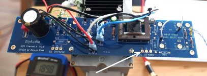
I think I see a red cable jacket through the empty PCB hole where Q1's Source pin will eventually be soldered (?). White arrowhead in attached image.
Does this mean that the circuit board is not connected to any Q1 or Q2, anywhere?
_
sorry, the picture is not so clear:
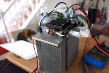
The whole output stage is done "point-to-point" on the heat sink, and the board provides the input stage and the bias regulator.
I'm going to use an old Mac G5 chassis, and to use the CPU cooler I need to move the MOSFETs off-board. I moved both MOSFETs, as well as R13/14, the gate stoppers R8/9 and also R10/11 off the board and to the heat sink. You can glimpse the negative half in the first picture, the positive half is on the other side of the sink. This way I can accommodate the two MOSFETs on the one sink -- well, I still have to see if this way I can safely remove the 80 Watt or so.
The connection to the board is then only Vcc/Vee/Output (the black wires), and the four lines for gate and "bias sensing" lines (the white/green twisted pairs).
Seems to work and is dead silent.
Attachments
First Watt M2 - 15dB gain
First Watt F6 - 14dB gain
I don't know if the DIYA clones vary from the factory specs for gain.
Someone please correct me if I'm wrong; I'm learning. I didn't think the max rated power output into load would affect the dBSPL all things remaining equal at a "lower" volume. Both amps at the same (let's say 1V) input signal - should be very close. I thought dBSPL was solely dependent on output voltage - assuming there is enough current available at the desired voltage. I can see the F6 having more oomph into a 4 ohm load at higher volumes, but at "testing" levels - that would surprise me.
Thanks, so they should both be very similar, and I have to figure out what's going on here.
I observed the ~7db difference (which was quite obvious from the start) by balancing left channel (M2X) and right channel (F6), using a pink noise test track, and changing the input level by DSP in ROON until the noise was coming from the middle between the speakers.
I'd say that should be good to 1-2 db or so.
Next step is to put in an input stage -- don't really expect this to change anything though, as the input buffer gain is supposed to be 1.
Cool implementation. 🙂
You could consider playing a tone around 60Hz to 100Hz and measuring the AC voltage at the inputs and then at the outputs of each. You could do it at a few levels if you'd like. That will tell you with a bit more certainty how different the gains are. It's not perfect, but it would likely be more indicative and is a slightly more direct measurement.
You've mentioned that it's making music, and you haven't mentioned anything sounding distorted or "off". So it should be a relatively low risk test to check your suspicion.
What is your source?I had expected the M2X to actually have higher gain than the F6, given the 1:5 auto former!
Without an input buffer your source is looking more or less straight at the Edcor.
So you might be loading the source very heavily.
Cool implementation. 🙂
You could consider playing a tone around 60Hz to 100Hz and measuring the AC voltage at the inputs and then at the outputs of each.
That's a great idea! Here's the result of playing a 60Hz sine wave tone, at 3 different volume levels:
M2X/F6:
0.05V/0.385V at a low level (x7.7/18dB)
0.20V/1.076V at a med level 2 (x5.4/14.6dB)
0.805V/3.55V at a high level 3 (x4.4/13dB)
So my aural leveling wasn't so bad (I estimated 7dB power/loudness while listening at the medium setting-> 14dB voltage). I guess there's a real effect here -- strange!
My setup is Allo Katana DAC -> Mesmerize B1 -> (no buffer stage) M2X(left channel)/F6(right channel)
Sorry, I am not sure I am understanding your data and/or I wasn't clear - likely both 😀
What I was attempting to describe was:
- Same output level from the B1M to each channel. No changes in Roon to compensate or intentionally center the image.
- Measure each input level (or just verify with the first measurement that they're equal on both channels).
- Measure each output level.
Compare.
Input M2x/F6 => Output M2x
Input M2x/F6 => Output F6
.
.
.
Did I misinterpret your results? I don't see the difference in the gains shown. Even with a DMM, I haven't seen that large a difference in gains at different input levels. Something seems odd... but it could be my measurements from the past were off.
If you're getting a really low input on the M2x w/o the buffer... two potential things. One clearly shows I know nothing about the B1M.
1) Can the pre-amp drive the load? See above post from Stanislav.
2) Is it wired properly? I can only parrot the recommendation.
Here are a couple notes I had in my file from Mark J when I had asked about trying the M2x without the input stage. I included the references to threads in case my links are broken.
Post #2327 - The diyAudio First Watt M2x
"If your preamp can deliver a 3.5 volt sinewave into a 500 ohm load then your intuition is right: you can run your M2x without any daughter card at all. That's how Nelson Pass designed the original M2, and then at the very end he added his version of Ishikawa so that customers with vacuum tube preamps or "passive preamps" could use and enjoy an M2 as well."
"Here is one simple way to do the bypass: Wayne's BA 2018 linestage in another thread." Post #752 in Wayne's BA Line Stage."
What I was attempting to describe was:
- Same output level from the B1M to each channel. No changes in Roon to compensate or intentionally center the image.
- Measure each input level (or just verify with the first measurement that they're equal on both channels).
- Measure each output level.
Compare.
Input M2x/F6 => Output M2x
Input M2x/F6 => Output F6
yes, that's exactly what I did: same input level each to F6 and M2X (just measured again, it's 0.155V for the 60Hz sine wave at medium level), resulting in 0.2V on the speaker terminals for the M2X, and 1.1V for the F6.
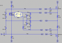
Ok, I got it -- unfortunately, I was a dummy who doesn't really get Ohms law...:
If I want to run the M2X without the input buffer I can't just replace the input stage with a wire -- I have to bridge R1 to connect the input directly to the auto-former. If I leave R1 in, which I did, and with the input impedance of the autoformer at ~300 Ohm, then R1 = 1K takes about 1K/1.3K ~ 77% of the input voltage, and the auto-former is left with less than a quarter of the input.
At least my measurement was consistent...the voltage gain then is (300/1300)*(5/1) ~ 1.15 = 1.2 dB, while the F6 has 15db, explaining the 7db loudness difference.
Ohm is winning again.
I apologize, I was stupid (and I believe somewhere in this or the F6 thread there is exactly that info...). Thanks to all, I learned something today. And the sound so far is great!
You can't beat the rap when it's Ohm's Law.
Please no mention of, "Rap" in conjunction with this lovely amplifier. 😛
- Home
- Amplifiers
- Pass Labs
- The diyAudio First Watt M2x