Maybe I miss something but I don't see how reducing the output resistors will help with driving heavy loads. We can have about a volt more output, but nothing more really. For example if I expect 16V into 4 ohms output, this is 4A current. 2V are lost in the power resistors. If I change them to 0.3ohms, I'll have 1.2V loss. Does 0.8V difference in the clipping voltage really matter? ... considering that idle current and thermal stability will be somewhat degraded.
Open loop gain in this amplifier is only defined with the speaker load connected. The output stage is a true current source with high output impedance. The connected load will define OLG and feedback amount. The original is made for 16 ohms. If we use the original schematic into 8 ohms then OLG is halved from what it would be into 16 ohms. Use 4 ohms and OLG is 1/4 of that.
It is a brilliant design and I want to build one.
Last edited:
Yeah, it's very cool design and is so interesting to play with it! The output stage is driven by current, not from the usual VAS, but this doesn't make the loudspeaker output a current source. I measured 0.09R output impedance into 4-ohm load at 10KHz, 1kHz, and 100Hz. The output impedance rises to 0.17R at 30Hz. I think this is very decent performance (with about 1m of speaker cable included), limited in the lowest octave by the output capacitor... The feedback is current type with all the benefits and implications.
The critical part is the correct drop across the splitter diodes and the capacitance of the splitter transistors. Less capacitance - faster to deplete the junctions and switch off the splitter transistors. Blomley talks about this in the article, but he uses standard 2N3904/2N3906 .... Tr5 "2N3905" must be a typo in the article. 2N3905 is PNP type just like the 2N3906. Schematic should read "2N3903" or "2N3904". The problem is that there is not much choice of suitable transistors today, just like back in the 70s 🙂 Definitely more options are available in SMT packages, but I can't find anything that looks significantly better than the BC5xx and 2N3904/06. Most devices on paper seem to have similar capacitance in the range of 4mA collector current.
I tried 2 x 1N4148 diodes, just because I had to 🙂 As expected the output idle current rose to 300mA and there was no range in the trimmers to decrease it. The amp turns into some sort of deep class-AB and have amazingly clean sine wave up to very high frequency. No crossover distortion at all of course, because there is not abrupt switching in the splitter! If anyone wants to run it like that, I'm sure it will be terrific amp, but for me heat is something I'd like to avoid. I also tried 1N5711 instead of BAT46. Might be just a bit better, but can't say for sure. 1N5711 has slightly bigger Vf drop than BAT46, so it is the better choice on paper. However there is no visible difference in the crossover distortion. I think faster splitter transistors will make more difference than playing with the diodes (unless 2 x 1N4148 are used and the amp runs hot).
Last edited:
Yes, the Blomley is very interesting. It is "current-steering".
The feedback makes the output impedance low of course. But the output stage on its own is high impedance unlike 99% of designs.
To keep the same amount of feedback (in dB) with a 4 ohm load we have to lower the voltage gain to 25, because of the OLG reduction.
In simulation it is quite stable. Now I have to build it.
Blomley specifically separated the splitting from the output bias and used fast switching transistors to "jump the gap" way, way faster than audible. A small bias to make the jump smaller, but NOT to eliminate it is used.The definition of transconductance I understand... Thanks for mentioning Tr2/Tr3 though! I found that Tr3 collector current changes by about 1mA for any 1mV of change on the base of Tr2. What threw me off initially was simulating the schematic with 4 ohms load. If the load is 16 ohm 1V/1A is the ratio. So, mystery solved! ... With 4 ohms it's more like 1V/2A.
With sine wave of about 300kHz the crossover distortion is well visible (screenshot attached)... Enough for trimmer adjustments just by watching for best response on the scope. In my prototype some 50-60mA give the cleanest sine wave. I was disappointed to see crossover distortion, but then I realized that most amplifiers don't even make it there in frequency response. I'll try other splitter transistors to see if there is any improvement.
2 x Schottky will bias the splitter in class C, to my understanding... with a band in the splitter crossover region where both Tr4/Tr5 are off. I think 1xSi and 1xSchottky is a fine combination.
After many trials to balance differently/better the input stage currents and feedback, I can confirm that what Blomley designed is the best overall 🙂 No need to change anything... I only made R9=6k2 because of lower power supply voltage (45V), and the feedback R5=120R to decrease the gain.
For more output power into heavy load either trimmers R20/R21 need to be increased, or R17/R18 decreased. Originally the current gain was set to 500/0.5=1000 by Blomley, but for more output power 1500 might be better. However that will require more idle current and also the thermal stability will suffer. With gain of 1000 and 45V supply I get about 20W/4ohm and this is good for me. I'll do some listening tests soon.
If you use a schottky and a silicon, that just turns the outputs on, Try 2 Schottkys - if it works without changing the output idle current at all temperatures that will be a useful contribution. Otherwise FIND a gold-bonded germanium diode.
Remember the splitters are rectifiers with level-shifting and NOT amplifiers. They are used in current mode because Si junctions are perfect current rectifiers. Turning them on with bias totally destroys that perfection, See Blomley's diagram of horrible VOLTAGE in the splitters Read Blomley's description of the splitters.
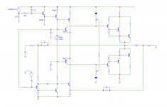
Here’s the new Blomley PCB, as I promised. This is not the final version, some refinements are needed yet. Not single-sided design, but the signal paths are much shorter and clearer in two-sided version. The numbering of the transistors is the same as can be seen in the original Blomley schematic. If anyone finds any errors please let me know.View attachment 1039074
One possibility is replacing the 22K resistor with a CCS that is temperature stable and ditch the diodes, using a trimpot to get the desired voltage (~0.9V). Add an electrolytic to the base of TR4, to ground. The same that is already present at TR5.
This CCS is very stable with temperature when dissipation is equal in the NPN and PNP, which is the case with the values shown. The Vbe vs. temp of the NPN and PNP cancel out. I chose LM336-5.0 voltage reference because it has low tempco, 20ppm/degC according to TI.
The 3600 ohm resistor is chosen to give ~1.4mA current and can be trimmed to make the speaker output 30V (or mid supply). BTW the supply to the Blomley must be regulated IMO.
The trimpot is adjusted to ~600 ohms so you can use a 1K trimmer.
RF and CF form a filter for the voltage reference and it might be possible to eliminate turn on thump by choosing a large time constant. CF should connect to the positive, as shown.
Attachments
Last edited:
Member
Joined 2009
Paid Member
I like your thinking.
To be clear, are you proposing to arrange for the CCS to track the temperature of TR4 and TR5 so that the resultant Vbe is stable for the phase splitting to be overall fixed regardless of temperature drift ?
To be clear, are you proposing to arrange for the CCS to track the temperature of TR4 and TR5 so that the resultant Vbe is stable for the phase splitting to be overall fixed regardless of temperature drift ?
I didn't think of temperature tracking between the CCS and TR4 and TR5. Do you think it is required?
I just proposed a very temp stable CCS, variation over 30 degree C is a couple of microamps if the transistors work with equal dissipation. It's a starting point I think.
I just proposed a very temp stable CCS, variation over 30 degree C is a couple of microamps if the transistors work with equal dissipation. It's a starting point I think.
Member
Joined 2009
Paid Member
I think it's worth considering that the end result you're after is stable phase splitting by TR4 and TR5. The voltage bias between their base junctions is part of the equation, but I assume the other part is the sum of the Vbe drops in TR4 and TR5. The key is the bias voltage that separates their base junctions relative to the voltage at their common emitters. At least I thought that was the way they work.
Yes, I understand, and you are correct of course. And to be honest I'm not familiar with the temp characteristics of the gold bonded germanium. So I just thought a good starting point is a stable bias voltage AND the possibility of adjusting it. There must be a point that is a good compromise over the required temp range.
I guess we can ask the question, what are the temp characteristics of that combo (1N916 + OA47) and how to replicate it with the CCS + trimmer.
I guess we can ask the question, what are the temp characteristics of that combo (1N916 + OA47) and how to replicate it with the CCS + trimmer.
Last edited:
Member
Joined 2009
Paid Member
I think you are on the right track with the CCS, it uses parts that are more common too. Can you arrange for the CCS to track the temperature of TR4 and TR5? Perhaps they just need to be physically pressed together like you would do with an LTP. I'm too lazy to figure it out right now but one of the CCS components will be the right choice to put in physical contact with TR4 and TR5 (if not then the bandgap reference could be replaced with a transistor wired as a diode etc.) and some tweaking afterwards - it's actually possible to simulate it all in LTSpice because you can specify the junction temperature of each transistor involved and set it as a parameter during the simulation. I used this method to design a proper bias control for the Naim amplifier. Sorry if it seems like I'm giving you work to do!
No problem, I can try to sim that. What I have used before is this parameter: T relative to global. I can change it for each BJT.
But it would be better if someone does it in solder!
But it would be better if someone does it in solder!
Bigun, I gave it some thought, tried some simulations, and this is the best I could come up with. Vbe tempco is aproximately -2mV/degC. At much lower currents such as the ones in the splitter the tempco can be as high as -2.6mV/degC, as Bob Pease explains in "what's all this vbe stuff anyhow", but that will not be important for us, it's just a reminder that there are assumptions with these rules of thumb. You would need a custom spice model to represent this. But as I said this is not important, we just need to aproximate the tempco to get consistent splitting over temperature. So we use -2mV/degC. Because we have two splitters, two Vbe drops, we need a bias voltage with -4mV/degC. With the trimmer set to aproximately 600 ohms, we need a CCS with -6.6uA/degC. I found that a common ring of two CCS has approximately half of that, according to Microcap. Not thermally coupled - just considering ambient temperature. So, this way we can probably get -2mV/degC for the splitter bias. I am satisfied with this compromise, I will build it like this, with a very well regulated supply.
Last edited:
OK, I just realized this: two schottkys + trimmer in conjunction with the temp stable CCS is a better approximation. I mean the CCS I posted previously with schematic. Schottkys have a tempco of -1 to -2mV/degC, but have a slightly lower Vdrop than needed, so we include a trimmer in series. Best to pick a Schottky with -2mV/degC.
Member
Joined 2009
Paid Member
good progress!
when you build it, try to arrange the tempco controlling elements so they are touching or close together
when you build it, try to arrange the tempco controlling elements so they are touching or close together
You could consider a constant current diode - these come in various current values see for details and graphs https://nz.mouser.com/datasheet/2/362/P22-23-CRD-1729293.pdf Temp can be set with a high value resistor - possibly with an NTC thermistor.OK, I just realized this: two schottkys + trimmer in conjunction with the temp stable CCS is a better approximation. I mean the CCS I posted previously with schematic. Schottkys have a tempco of -1 to -2mV/degC, but have a slightly lower Vdrop than needed, so we include a trimmer in series. Best to pick a Schottky with -2mV/degC.
Last edited:
Some OA47 with military designation CV7127 circa 1975 on sale for £1ea. Long established supplier:
https://www.langrex.co.uk/products/oa47cv7127-germanium-diode-do-7-gold-bonded-x-1pc/
https://www.langrex.co.uk/products/oa47cv7127-germanium-diode-do-7-gold-bonded-x-1pc/
The plots above look really good. I have had this project on the back-burner for a while. I have a couple of PCB's laid out with thru hole or smt parts.
Harmonic distortion is not as serious as the non-harmonic variety, the odd order overtones are the trouble, 3rd, 5th, 7th etc.
The human ear generates its own even order harmonics, we like it. Push-pull amps tend to suppress even order harmonics.
%THD+Noise is more of a figure of merit than a real ear experience.
LTspice defaults power supplies to 0 Ohm, which does not happen in real life, (zero anything is more of an abstraction) better put some more realistic numbers here, and use their capacitor models with parasitics for power supply bypassing.
Obviously the ear is better at sound than simulations and numbers.
I know LTspice can output a .wav file, maybe it can also use one for input?
I used BC546B and BC556B as splitters. The typical characteristics of these are not identical the former is more linear in its' 50uA working range outside of the turn on area. The BC556B plot has a degree of slopeYeah, it's very cool design and is so interesting to play with it! The output stage is driven by current, not from the usual VAS, but this doesn't make the loudspeaker output a current source. I measured 0.09R output impedance into 4-ohm load at 10KHz, 1kHz, and 100Hz. The output impedance rises to 0.17R at 30Hz. I think this is very decent performance (with about 1m of speaker cable included), limited in the lowest octave by the output capacitor... The feedback is current type with all the benefits and implications.
The critical part is the correct drop across the splitter diodes and the capacitance of the splitter transistors. Less capacitance - faster to deplete the junctions and switch off the splitter transistors. Blomley talks about this in the article, but he uses standard 2N3904/2N3906 .... Tr5 "2N3905" must be a typo in the article. 2N3905 is PNP type just like the 2N3906. Schematic should read "2N3903" or "2N3904". The problem is that there is not much choice of suitable transistors today, just like back in the 70s 🙂 Definitely more options are available in SMT packages, but I can't find anything that looks significantly better than the BC5xx and 2N3904/06. Most devices on paper seem to have similar capacitance in the range of 4mA collector current.
I tried 2 x 1N4148 diodes, just because I had to 🙂 As expected the output idle current rose to 300mA and there was no range in the trimmers to decrease it. The amp turns into some sort of deep class-AB and have amazingly clean sine wave up to very high frequency. No crossover distortion at all of course, because there is not abrupt switching in the splitter! If anyone wants to run it like that, I'm sure it will be terrific amp, but for me heat is something I'd like to avoid. I also tried 1N5711 instead of BAT46. Might be just a bit better, but can't say for sure. 1N5711 has slightly bigger Vf drop than BAT46, so it is the better choice on paper. However there is no visible difference in the crossover distortion. I think faster splitter transistors will make more difference than playing with the diodes (unless 2 x 1N4148 are used and the amp runs hot).
One of the main points of the circuit according to Linsley-Hood was to avoid temperature issues with the output stage. The problem of setting bias currents for the output stage is then removed to the splitters. I used BC546B and BC556B in simulations. These give acceptable but not stellar results at 1kHz with low output quiescent current. Unfortunately things fall apart at 20kHz. Linsley-Hood drew a simplified version of the circuit using an op.amp and in this made use of constant current sources in three places. I can post the circuit if anyone is interested.Yeah, it's very cool design and is so interesting to play with it! The output stage is driven by current, not from the usual VAS, but this doesn't make the loudspeaker output a current source. I measured 0.09R output impedance into 4-ohm load at 10KHz, 1kHz, and 100Hz. The output impedance rises to 0.17R at 30Hz. I think this is very decent performance (with about 1m of speaker cable included), limited in the lowest octave by the output capacitor... The feedback is current type with all the benefits and implications.
The critical part is the correct drop across the splitter diodes and the capacitance of the splitter transistors. Less capacitance - faster to deplete the junctions and switch off the splitter transistors. Blomley talks about this in the article, but he uses standard 2N3904/2N3906 .... Tr5 "2N3905" must be a typo in the article. 2N3905 is PNP type just like the 2N3906. Schematic should read "2N3903" or "2N3904". The problem is that there is not much choice of suitable transistors today, just like back in the 70s 🙂 Definitely more options are available in SMT packages, but I can't find anything that looks significantly better than the BC5xx and 2N3904/06. Most devices on paper seem to have similar capacitance in the range of 4mA collector current.
I tried 2 x 1N4148 diodes, just because I had to 🙂 As expected the output idle current rose to 300mA and there was no range in the trimmers to decrease it. The amp turns into some sort of deep class-AB and have amazingly clean sine wave up to very high frequency. No crossover distortion at all of course, because there is not abrupt switching in the splitter! If anyone wants to run it like that, I'm sure it will be terrific amp, but for me heat is something I'd like to avoid. I also tried 1N5711 instead of BAT46. Might be just a bit better, but can't say for sure. 1N5711 has slightly bigger Vf drop than BAT46, so it is the better choice on paper. However there is no visible difference in the crossover distortion. I think faster splitter transistors will make more difference than playing with the diodes (unless 2 x 1N4148 are used and the amp runs hot).


- Home
- Amplifiers
- Solid State
- The Blomley Class B amplifier