A quick and dirty RLCRLC
Very interesting. What algo do you use to generate a dsd waveform? Or is it just pwm?
Edit: found a nice example for delta-sigma generation in the AA of all places. Maybe even i can manage to use this in simulation.
Last edited:
Can you post some pictures of your implementation?
Same result with either the pcb or the flip flop on veroboard (shorter wiring).
I connected pin3 and 5 on the amanero to pins 2 and 12 on the flip flop and pin 4 on the amanero to pins 3 and 11 on the flip flop. Finally, the amanero ground (e.g. pin 8 on the amanero) is connected to the supply ground for the flip flop.
I will post pictures later.
Thanks
Giulio
Very interesting. What algo do you use to generate a dsd waveform? Or is it just pwm?
Edit: found a nice example for delta-sigma generation in the AA of all places. Maybe even i can manage to use this in simulation.
It was made for me by mansr on the computeraudiophile forums. At that time, his software only did up to DSD64 DoP out. I am trying to get a working compile of the new version of it right now. Note that it is not DSD but "DSD over PCM." which is just DSD in a wav container.
Will make sample files once I get it working.
Would like to read anything that you find helpful
I don't get it. All my BiB builds have been unconditionally stable.
Have your tried BiB powering the FlipFlop?
merlin, my experience with Ref-D so far is that I prefer BiB even for digital. I had couple of Ref-D's in my DAC but I replaced them over time for BiB's after listening comparisons. Both my BiB and Ref-D implementations are stable and quiet, even without the zobel network!For digital I use Reflektor-D.
Have your tried BiB powering the FlipFlop?
If you use the flip flop board stacked on top of jlsounds xmos as intended, the power supply is shared between the isolated part of the board and the flip flops. In my case this power is provided from the BiB.
Six important conditions for a good noDAC (I was one of the first to make one):
1) Complete isolation from PC supply
2) Very high sampling rate (DSD256 or better DSD512)
3) Possibly 45.158Mhz/49.152Mhz audio oscillator of the maximum quality (this is not 44.1 kHz signal!)
3) First order filter to avoid phase problems (or eventually a very sophisticated superior order filter)
4) Very high quality power supply (here I prefer battery lifepo4 for various reasons, the first one lack of possible power supply interactions with the circuit)
5) Possibly transformer isolation from following circuits
6) Output stage with amplification of around 11-12 dB
1) 2) 4) 5) are very important for noiseless output
6) is very important to obtain a good bass output and a more solid sound.
I remember that an impedance mismatch between noDAC output and amplifier/preamplifier input (for example the use of low input impedance solid state preamp) could lead to a thin sound like the sound of some passive preamplifiers.
If someone want to test it is necessary to use a real PDM signal.
Same result with either the pcb or the flip flop on veroboard (shorter wiring).
I connected pin3 and 5 on the amanero to pins 2 and 12 on the flip flop and pin 4 on the amanero to pins 3 and 11 on the flip flop. Finally, the amanero ground (e.g. pin 8 on the amanero) is connected to the supply ground for the flip flop.
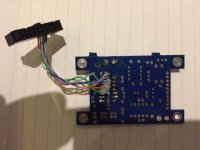
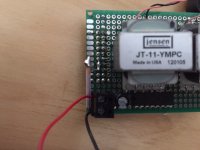
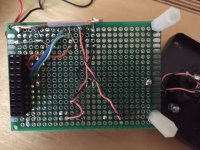
Here are the pictures. The first one is for the PCB in this thread, the other two for the point-to-point implementation.
Just in case is relevant, the flip flop power supply is 3.3v from a Lifepo4 battery.
Thanks,
Giulio
Attachments
Last edited:
Giulio the flip flop chip needs 5V.
Merlin thanks. Could you elaborate please? The datasheet writes "Wide supply voltage range from 2.0 to 6.0V".
Is the required supply voltage for the flip flop related to the clock voltage (3.3V)?
TIA
Do You know any good converter? Sound, on the fly, from HQPlayer, Daphile... is getting beater and beater so finding good converter is not so easy.
Maybe AK4137 SRC is what you need. It will do PCM to DSD on the fly.
Last edited:
Maybe AK4137 SRC is what you need. It will do PCM to DSD on the fly.
Maximum DSD256
Ray do you know if the wew Diyinhk USB to I2S 768Khz - DSD512/1024* Converter http://www.diyaudio.com/forums/vendors-bazaar/290015-new-usb-i2s-768khz-dsd512-1024-converter.html is pin compatible with the flip-flop & SE boards?
Felipe
I have changed from an XMOS PCB.................
Newest Xmos U8 USB 384K 32B Module I2S SPDIF Output Support DSD for ES9018 DAC | eBay
to the one mentioned above and am getting O/P but am still getting the same background noise/hash/hf mush that I was getting with the first PCB I used.
I am taking the DSD L & R channels and passing them through a Filter the same as in Post 936.
Just to clarify, you guys are getting just Music? No background noise/hash? S/N to compare with a PCM DAC?
I've tried separate, quiet, PSU's for everything.
It is actually quieter (still not listenable(to me)) with DSD64, getting progressively worse with DSD128 and DSD256.
Any thoughts whatsoever greatly appreciated.
P.
Just to clarify, you guys are getting just Music?
Yes
No background noise/hash?
None that I can hear
S/N to compare with a PCM DAC?
I have no means of measuring this but it sounds good
Any thoughts whatsoever greatly appreciated.
You're not using any isolation?
I'm suspicious of your USB board.
Ray
I have changed from an XMOS PCB.................
Newest Xmos U8 USB 384K 32B Module I2S SPDIF Output Support DSD for ES9018 DAC | eBay
to the one mentioned above and am getting O/P but am still getting the same background noise/hash/hf mush that I was getting with the first PCB I used.
I am taking the DSD L & R channels and passing them through a Filter the same as in Post 936.
Just to clarify, you guys are getting just Music? No background noise/hash? S/N to compare with a PCM DAC?
I've tried separate, quiet, PSU's for everything.
It is actually quieter (still not listenable(to me)) with DSD64, getting progressively worse with DSD128 and DSD256.
Any thoughts whatsoever greatly appreciated.
P.
As pointed Ray used isolated I2S, also power the USB-I2S with dedicate PSU not BUS powered from the PC, if you use flip flop better check with the scope looking for PSU oscillation.
Felipe
Same result with either the pcb or the flip flop on veroboard (shorter wiring).
I connected pin3 and 5 on the amanero to pins 2 and 12 on the flip flop and pin 4 on the amanero to pins 3 and 11 on the flip flop. Finally, the amanero ground (e.g. pin 8 on the amanero) is connected to the supply ground for the flip flop.
I will post pictures later.
Thanks
Giulio
Your picture of the FlipFlop PCB shows most of it unpopulated?
On the veroboard are you using just the transformers with no LP filter?
Are you using any isolation between Amanero and flipflop PCB or veroboard?
Anyway, ignoring the mute function for now and referencing the Amanero datasheet;
http://www.amanero.com/drivers/combo384-D.pdf
I believe connections should be as below:
Amanero pin3 >> FlipFlop PCB header pin 13 >>FlipFlop IC pin 2
Amanero pin4 >> FlipFlop PCB header pin 15 >> FlipFlop IC pins 3 & 11
Amanero pin5 >> FlipFlop PCB header pin 14 >> FlipFlop IC pin 12
+ve >> FlipFlop PCB header pin 12 >> FlipFlop IC pins 1, 4, 10, 13 & 14
Ground >> FlipFlop PCB header pin 11 >> FlipFlop IC pin 7
FlipFlop IC differential outputs are on pins 5/6 and 8/9
What FlipFlop device are you using?
Are you decoupling the FlipFlop power supply (47uF/100nF in parallel located close to the FlipFlop power supply pin)?
You only need to make connections to FlipFlop PCB pins 1-10 if you're using the mute and DSD indicator functions - we can cover that later.
Ray
Last edited:
Thanks Merlin and Ray
I have not populated the muting section of your pcb. I also thought the transformers would provide enough filtration.
That's what I have. You do not mention connecting the amanero ground (or whatever usb2dsd converter) ground to the flip flop pcb ground. 😕
I have tried using a 5V (switch mode) supply instead of the 3.3v battery. I get some loud ground loop hum but still no music.
Best,
Giulio
Your picture of the FlipFlop PCB shows most of it unpopulated?
On the veroboard are you using just the transformers with no LP filter?
I have not populated the muting section of your pcb. I also thought the transformers would provide enough filtration.
No.Are you using any isolation between Amanero and flipflop PCB or veroboard?
I believe connections should be as below:
Amanero pin3 >> FlipFlop PCB header pin 13 >>FlipFlop IC pin 2
Amanero pin4 >> FlipFlop PCB header pin 15 >> FlipFlop IC pins 3 & 11
Amanero pin5 >> FlipFlop PCB header pin 14 >> FlipFlop IC pin 12
FlipFlop IC differential outputs are on pins 5/6 and 8/9
Ground >> FlipFlop PCB header pin 11 >> FlipFlop IC pin 7
That's what I have. You do not mention connecting the amanero ground (or whatever usb2dsd converter) ground to the flip flop pcb ground. 😕
I am confused about IC pins 1,4,10,13. I understood they were to be unterminated.+ve >> FlipFlop PCB header pin 12 >> FlipFlop IC pins 1, 4, 10, 13 & 14
SN74HC74N - TEXAS INSTRUMENTS - Flip-Flop, with Clear and Preset,Complementary Output, Positive Edge, D, 15 ns, 60 MHz, 5.2 mA, DIP | Farnell element14What FlipFlop device are you using?
Yes.Are you decoupling the FlipFlop power supply (47uF/100nF in parallel located close to the FlipFlop power supply pin)?
I have tried using a 5V (switch mode) supply instead of the 3.3v battery. I get some loud ground loop hum but still no music.
Best,
Giulio
Last edited:
Hi there! I'm here again for a n00b question.
Finally received the transistors and the pot... Got Mute delay working (still have to wire it properly) but the DSD LED is always on, since I have circa 3V from pin8...
I'm powering the dirty side by USB, could be that the reason?
Finally received the transistors and the pot... Got Mute delay working (still have to wire it properly) but the DSD LED is always on, since I have circa 3V from pin8...
I'm powering the dirty side by USB, could be that the reason?
- Home
- Source & Line
- Digital Line Level
- The Best DAC is no DAC