I will take the +5V coming from the USB.
Yep, that will do it.
When jumper J1 is installed what's going on Ray?
It's normal LED lights when no playing music?
It's normal LED lights when no playing music?
When jumper J1 is installed what's going on Ray?
It's normal LED lights when no playing music?
http://www.diyaudio.com/forums/digital-line-level/273474-best-dac-no-dac-130.html#post4685395
Yes, the LED will stay on until you send it some PCM - not recommended but you can test it by disconnecting audio output if you want.
Thanks Ray, so all populate with timer IC and bridge J1 is doing "nothing"?
If you wish to use Fabio's delay circuit, populate all of the components and omit J1.
If you wish to use the original delay circuit omit the timer IC and bridge J1.
If you wish to use Fabio's delay circuit, populate all of the components and omit J1.
If you wish to use the original delay circuit omit the timer IC and bridge J1.
With all components populated and omit J1 "no sound"
With all components populated with timer IC and bridge J1 "sound" but still noise starting the music.
With all components populated with timer IC and bridge J1 "sound" but still noise starting the music.
More test: omit the timer IC and bridge J1 works like a charm, no pops no noise.
Why don't sound using Fabio's delay circuit populating all of the components and omit J1?
Why don't sound using Fabio's delay circuit populating all of the components and omit J1?
With Fabio's circuit you have to 'tweak' the preset to minimise the pops - trial and error I'm afraid.
Ray
Ray
The isue with Fabio's circuit is that I have "no sound"!!!!!!!!!!!!
Have you tried adjusting the preset? Maybe it is in a position that means the relay is 'locked' in the mute position.
I guess preset is the trimmer if yes I will try tomorrow, now is too late.
Good night Ray.
Good night Ray.
Last edited:
It looks you've inverted channels' return:Pic how I connected the mute, is OK?
Mute 1 Pin 1 = channel 1 signal (or channel 1 output +)
Mute 1 Pin 2 = ground (or channel 1 output -)
Mute 2 Pin 1 = channel 2 signal (or channel 2 output +)
Mute 2 Pin 2 = ground (or channel 2 output -)
Ray
I guess preset is the trimmer if yes I will try tomorrow, now is too late.
Good night Ray.
Yes, preset = trimmer pot.
Regarding mute connections, should be as ghiglie has pointed out.
![WP_20160424_001[1].jpg](/community/data/attachments/507/507181-06ff333a151742e8ddb1f8bc9e2fb41d.jpg?hash=Bv8zOhUXQu)
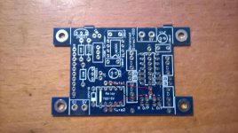
I did not draw well the connections, attached real pic, is OK?
Looks OK
Ray do you know if the wew Diyinhk USB to I2S 768Khz - DSD512/1024* Converter http://www.diyaudio.com/forums/vendors-bazaar/290015-new-usb-i2s-768khz-dsd512-1024-converter.html is pin compatible with the flip-flop & SE boards?
Felipe
Felipe
Ray do you know if the wew Diyinhk USB to I2S 768Khz - DSD512/1024* Converter http://www.diyaudio.com/forums/vendors-bazaar/290015-new-usb-i2s-768khz-dsd512-1024-converter.html is pin compatible with the flip-flop & SE boards?
Felipe
I can't give a definitive answer but I imagine it presents DSD-L and DSD-R on its header pins; that's all you would need for the SE board. For the Balanced board you need a master clock signal for the FlipFlop device; section 7 of the user guide on the webpage describes a hack to get this.
No isolation/reclocking though, would have to be offboard should you consider it necessary.
Ray
- Home
- Source & Line
- Digital Line Level
- The Best DAC is no DAC