Ray the Pin numbers are as per attached picture or inverted?
Attachments
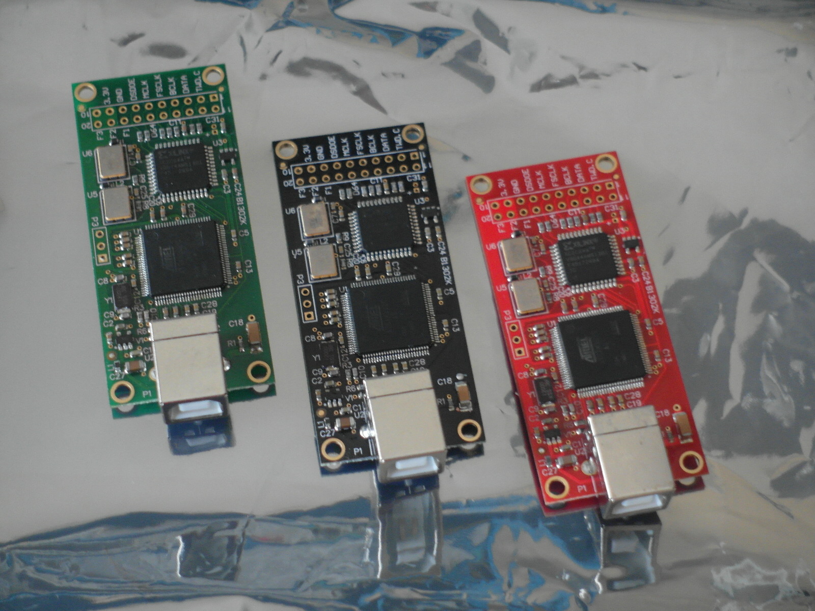
![WP_20160417_001[1].jpg](/community/data/attachments/497/497287-b884bc60baa183e7dc3651167324b833.jpg?hash=uIS8YLqhg-)
Last edited:
The balanced output goes to a balanced shunt attenuator then to a Broskie BCF Bal to SE buffer.
Ray what is the max output signal from BCF?
Ray the Pin numbers are as per attached picture or inverted?
It doesn't actually matter as the pins are completely isolated from everything other than the relay.
Ray
Ray what is the max output signal from BCF?
BCF is unity gain so it'll be around 1.2V; I've not actually measured it.
Ray
It doesn't actually matter as the pins are completely isolated from everything other than the relay.
Ray
Thank you
Felipe
BCF is unity gain so it'll be around 1.2V; I've not actually measured it.
Ray
Thank you, I measured around that value when feed bcf from the dac.
Is output level from the ff module always the same 2.4v? I mean it is not dependent on usb—i2s card type?
As you've used an IC socket for the NE555 you can have both mute options available if you use a header and removable jumper instead of soldering a link across J1. That's what I have done;
An externally hosted image should be here but it was not working when we last tested it.
There's a schematic here;
http://www.diyaudio.com/forums/digital-line-level/273474-best-dac-no-dac-94.html#post4630381
No.
Mute 1 Pin 1 = channel 1 signal (or channel 1 output +)
Mute 1 Pin 2 = ground (or channel 1 output -)
Mute 2 Pin 1 = channel 2 signal (or channel 2 output +)
Mute 2 Pin 2 = ground (or channel 2 output -)
Ray
Thanks again Ray.
I've seen you are using the pin on both, as I did. How are you linking them?
I'm now using these FlipFlop devices, which work well in my project, but it's up to you; I'm not recommending them above any other FlipFlops because they sound better or anything like that.
https://uk.farnell.com/webapp/wcs/stores/servlet/ProductDisplay?msg=&catalogId=15001&CMP=AFC-AN-UK-ALL-473347&langId=44&storeId=10151&krypto=yJNBBwaPlFA7MjWSrCTe1pFitf0%2FH2e2uPp89cMMVSwPOB2jidbP7wAmASMCmgSc3Bv1ih4QZTfY%0A9Trm%2BmjcfiGg6qiOldeqj3joIQ%2FZzng%3D&ddkey=http:Logoff
Ray
Thanks for all of your efforts on this, Ray! I'm putting together a parts order and want to maximize/optimize flip-flop voltage out. I find this link to be incorrect. Could you point me to your preferred part? TIA, Frank
Thanks again Ray.
I've seen you are using the pin on both, as I did. How are you linking them?
Assuming you're asking about J1, I use something like this. It just pushes onto the header pins.
M7581-05 - HARWIN - Jumper (Busbar), Jumper Socket, Pin Headers, 2 Ways, 2.54 mm | Farnell element14
Thanks for all of your efforts on this, Ray! I'm putting together a parts order and want to maximize/optimize flip-flop voltage out. I find this link to be incorrect. Could you point me to your preferred part? TIA, Frank
The FlipFlops I've used are Texas Instruments, part number CD74ACT74E.
Ray
Thank you, I measured around that value when feed bcf from the dac.
Is output level from the ff module always the same 2.4v? I mean it is not dependent on usb—i2s card type?
Hazard500 measured the output of his project. He's using a FlipFlop with the balanced output going to a pair of Llundahl transformers. He reported;
...I have measured the output of my no-DAC. I created a 440Hz, 0dB test signal using Audacity as a 16 bit wav file. Upsampling to DSD256 via HQPlayer, I measured 1.55V at the output of the transformer.
If you want to know more about Hazard's setup refer to post #1 of the thread.
Ray
Assuming you're asking about J1, I use something like this. It just pushes onto the header pins.
M7581-05 - HARWIN - Jumper (Busbar), Jumper Socket, Pin Headers, 2 Ways, 2.54 mm | Farnell element14
No, I was still talking about Mute1&2, just wondering how you'll use them - just 'cause as you've seen I have same 2pin strip soldered.
I was plenty of 2pin female sockets I used to salvage from old PC chassis... Wish I had kept them so I could try them here.
I have to update the XMOS firmware, got the two PSUs and I am ready to go. Thanks for your efforts and support!
M
I use this sort of thing;
Du Pont header pin crimp connectors | eBay
Ray
That's just what I was referring to, I have a bag of them... somewhere. Yet cabled - you can get them from old computers, they are used for LEDs and reset switch (2pin) and come splitted or 3pins for ATX power button.
Well, this time a simple update. I have to particular findings, but I managed to update the JLSounds with latest firmware from Joro (quite challenging for me), got the partially finished NoDAC SE board and measured 1,65v in Output on both channels. Perfect!
Now, I have to put together the offboard coupling caps - I've just a pair of 2,2uF Arcotronics and I'll test the result with my NAD C325BEE.
Again, thanks Ray for your immense and patient support!
Now, I have to put together the offboard coupling caps - I've just a pair of 2,2uF Arcotronics and I'll test the result with my NAD C325BEE.
Again, thanks Ray for your immense and patient support!
Ray
For non JLSounds owners could you let us know where we have to connect pins 1-10 in others USB-I2S boards or isolators?
TIA
Felipe
For non JLSounds owners could you let us know where we have to connect pins 1-10 in others USB-I2S boards or isolators?
TIA
Felipe
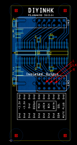
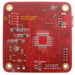
Attachments
Last edited:
Ray
For non JLSounds owners could you let us know where we have to connect pins 1-10 in others USB-I2S boards or isolators?
That's a bit of an ask, especially as I only use the JLSounds board so have no familiarity with other boards. I'll try to guide you in a general sense.
Pins 1 & 2 are power (5V DC) and ground. I suggest you connect these via a terminal block, located right next to pin 1. Remember the mute section of the board is completely isolated from the LP filter section. If you are using isolation between the USB board and the LP filter section I strongly suggest that you ground the mute section to the 'dirty' side ground (as it would be if plugged onto a JLSounds board).
Pins 3, 4, 5, 6 and 9 are not used.
Pin 10 is another ground connection, the same as pin2.
The connections to pin 7 and 8 will need you to research the specifics of your particular USB board and reconcile it against the JLSounds documentation.
http://jlsounds.com/uploads/Specifications.pdf
Pin 7 is the trigger connection for the mute circuit and you'll need to connect it to the Codec reset equivalent for your board (if an equivalent is available, if it isn't you'll not be able to trigger the mute relay)
Pin 8 is the trigger connection for the DSD indicator LED. You'll need to connect it to the Data Flag equivalent for your board.
Of course, for both 7 & 8, not only do you need the equivalents to the Codec and Data flags presented by your USB board, but the trigger voltage needs to be correct too (for example to light the DSD indicator LED, your USB board must provide a +3.3V voltage to pin 8 when DSD material is playing).
Looking at the Amanero documentation,
http://www.audiodesignguide.com/PureDSD/combo384-D.pdf
it looks as though you need to connect;
Mute trigger - Amanero pin 11 >> DSD board pin7
DSD Indicator - Amanero pin 7 >> DSD board pin 8
Ground - Amanero pin 13 >> DSD board pin 2
Power - connect DSD board pin 1 to your 5V Amanero power supply
I don't want to be responsible for any damage to people's USB boards so it is for you to check and confirm these connections. It shouldn't be difficult to check the output pins of the amanero (or other board) to see what they are presenting under what conditions.
I hope that points you in the right direction.
Ray
Last edited:
Thanks Ray really appreciated your help.
Felipe
No problem Felipe, I hope that enables you to get the mute section working.
Have you now satisfactorily resolved the noise issues with playback that you were experiencing?
Ray
- Home
- Source & Line
- Digital Line Level
- The Best DAC is no DAC