

I like the colour of that Clarity cap and it seems like it will fit. Some Pass stuff uses Clarity caps so you really can't go wrong.
This guy, on the other hand, looks too big. 🙂 :
https://www.partsconnexion.com/MIFLEX-87537.html
(If they aren't so expensive I would get one just for the amusement value of a cap so large...)
This guy, on the other hand, looks too big. 🙂 :
https://www.partsconnexion.com/MIFLEX-87537.html
(If they aren't so expensive I would get one just for the amusement value of a cap so large...)
Very nice job, sov! Seems like a snug fit 🙂
Now,
While you have it in the clear and can see everything.
Work out how you are going to (safely) get to R10 and, or R11 to measure bias.
You need to be very sure that whatever you put into the tight space does not short out! 🤔 🤔
While you have it in the clear and can see everything.
Work out how you are going to (safely) get to R10 and, or R11 to measure bias.
You need to be very sure that whatever you put into the tight space does not short out! 🤔 🤔
One of my probes once fell off the leg, caused a fire. A real burning amp 🙂Now,
While you have it in the clear and can see everything.
Work out how you are going to (safely) get to R10 and, or R11 to measure bias.
You need to be very sure that whatever you put into the tight space does not short out! 🤔 🤔
I feel like I've been working on this project since forever...
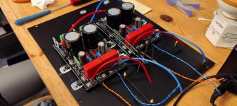
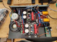
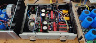
But, I've made good progress recently. Both the PSUs and amp are working. I'm currently powering the circuit from a bench top PSU providing +/-32V, BiB-regulated to the nominal +/-24V supply voltages.
Bringing up the PSU was a bit challenging as I had to monitor the biasing procedure for both channels (four pots in total) and the regs' output voltages (another four pots) simultaneously. All went well though, and all voltages are perfectly within specs.
As you can see, I'm going for a big fat star ground with this build. I hope the ground layout will work as planned.
Next up is input and mains wiring!
Attachments


A very, very nice build! Excited to see the end result. PS: if the gnd scheme doesn’t work out as planned, I recommend testing the glb from the Pearl 2 build guide (Building a Pearl 2).I feel like I've been working on this project since forever...
But, I've made good progress recently. Both the PSUs and amp are working. I'm currently powering the circuit from a bench top PSU providing +/-32V, BiB-regulated to the nominal +/-24V supply voltages.
Bringing up the PSU was a bit challenging as I had to monitor the biasing procedure for both channels (four pots in total) and the regs' output voltages (another four pots) simultaneously. All went well though, and all voltages are perfectly within specs.
As you can see, I'm going for a big fat star ground with this build. I hope the ground layout will work as planned.
Next up is input and mains wiring!
Thanks guys 🙂 with a little luck I'll be able to complete the amp in the next couple of days.
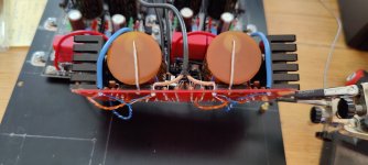
The markings on the caps are measured capacitance and the orientation of the outer foil. Details see https://www.diyaudio.com/community/...search-custom-made.380821/page-2#post-6909736 (post #36)
The markings on the caps are measured capacitance and the orientation of the outer foil. Details see https://www.diyaudio.com/community/...search-custom-made.380821/page-2#post-6909736 (post #36)
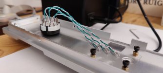
Let's see, a couple more pics from the input wiring, ventilation holes (next to the big resistors in the PSU), mains wiring and the front panel.
Attachments

Very nice, a tight build!
I don’t understand the smaller tranny—powers the selector board? And the second ubib will be powered with?
I don’t understand the smaller tranny—powers the selector board? And the second ubib will be powered with?
Tea-bag went that extra mile and built them into his simplistic phono stage… (among many others…)This guy, on the other hand, looks too big. 🙂 :
https://www.partsconnexion.com/MIFLEX-87537.html
(If they aren't so expensive I would get one just for the amusement value of a cap so large...)
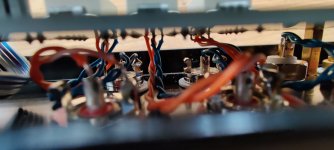
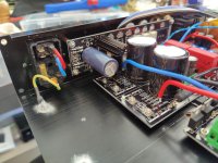
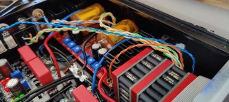
Hi Rodeodave, A potential issue that I can see in your grounding scheme is that it appears that you have connected the power supply ground that is right after your rectifiers to the central ground. That will inject noise into your audio circuit.
Attachments

I'm treating the rectifiers as if they were off board, the ground traces on the regulator pcb are cut right after the diode bridges. The second (upper) regulator is fed pos/neg voltage from the diode bridges via the red/blue wire. All grounds from the bridges, the regs and the amp are collected at the star ground.
Might work, might have to split the regulator ground further, we'll see.
Might work, might have to split the regulator ground further, we'll see.
Ben is seldom absolute, still always right. When he is absolute, means he is doubly almost certainly right 🙂That will inject noise into your audio circuit.
audio ground is not chassis/safety ground.
Last edited:
Audio ground and chassis ground are completely separate and electrically isolated from each other. The star ground is held in place by a nylon standoff, there is no connection to chassis ground.Ben is seldom absolute, still always right. When he is absolute, means he is doubly almost certainly right 🙂
audio ground is not chassis/safety ground.
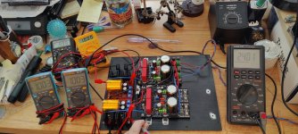
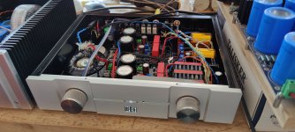
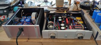
Alright, pretty much done here. Just waiting for a new transformer for the input select and attenuator PSU, which I'm currently powering from a wall wart supply.
I'm happy to report that otherwise the pre works just as planned. I'm currently listening to it though a modified diy F4 headphone amp and the HD800. No hum, neither on the scope nor through the headphones.
For now I've set the distortion to -85dB (1V output, so -85dBV), with the second harmonic slightly dominant over third, and negative phase second. This just might have become my new favorite preamp.
Attachments

Thanks for the feedback y'all 🙂
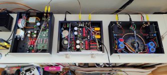
I have now listened to the preamp in my speaker setup for a couple of hours. The pre replaced a DCB1, over which the BA3 - to my ears - has notable improvements in bass slam and resolution. Very pleasant still, I believe thanks to 2nd harmonic dominance.
However, I'm encountering an interesting problem with hum(!), which I think somehow stems from the volume pot. I did not encounter this problem with the headphone setup. The source (dam1021) is completely free of hum, so I would excluded that as the culprit. The power amp (lpuhp) is a bit finicky concerning hum free operation, but the volume pot is at the input of the pre, thus isolated from the power amp through the preamp. I would therefore also exclude the power amp as the culprit.
The volume pot is a Khozmo 10k relay based attenuator, make before break, Amtrans AMRG resistors.
So with the volume at 0 (-60dB from input), there's zero hum. Turning up the volume to 30 (-30dB from input) there is a very slight increase of hum, just barely audible with the ear right next to the speaker (power amp gain at +15dB). With the volume going from 30 to 31 (1dB step), there's a significant increase in hum. There's a bunch of relays clicking in the Khozmo attenuator, so I suspect there's some impedance change going on. The hum further increases going up to 62 (-1dB from input). Going to 63 (0dB), the hum completely(!) disappears again.
Really strange behavior. Gonna investigate some more in the coming days.
Attachments
- Home
- Amplifiers
- Pass Labs
- The BA-3 as preamp build guide