Really, brand or series is not going to make that much difference as long as the temp co is low and the tolerance is low as well.
True...I even used the Xicon 50ppm 1% metal films in one BA-3.
The RN55 is a Mil-spec resistor, and has a 100% thermal de-rate. It's a 1/4W resistor, but the specs say it's to be used for 1/8W.
The CMF55 (same resistor, different spec sheet) differs only in the "max" watt rating and that the CMF can be built with steel or copper leads, where the RN must be copper.
SO... Use the RN55 if you have them. I do. 🙂
Thank you for explaining the differences.
6L6,
I noticed that you have raised the R10, R11 resistors off the board. Are they going to be getting hot? I have just mounted my 1/4W resistors to the board. Should I change. I looked around if it was mentioned as higher wattage resistor and hence defaulted to 1/4W Dale.
Cheers.
I noticed that you have raised the R10, R11 resistors off the board. Are they going to be getting hot? I have just mounted my 1/4W resistors to the board. Should I change. I looked around if it was mentioned as higher wattage resistor and hence defaulted to 1/4W Dale.
Cheers.
The resistors that are lifted on my PCB are those that need to have a DMM attached when setting the bias... You really need 3 meters, and preferably with clip-lead ends to set the bias.
The raised resistors merely give a place to clip upon. 😀
The raised resistors merely give a place to clip upon. 😀
The resistors that are lifted on my PCB are those that need to have a DMM attached when setting the bias... You really need 3 meters, and preferably with clip-lead ends to set the bias.
The raised resistors merely give a place to clip upon. 😀
Thanks. Got it.
Cheers.
I do not have 10 mA JFET pair but a 17 mA JFET pair. Can I use the pair I have? Do I have to change any resistor values or does it self bias to 8 mA?
Thanks in advance.
Cheers
Thanks in advance.
Cheers
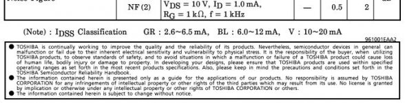
anil , 17mA mean V grade ?
Not necessarily right. There are outliers in BL grade as well. Mine is BL grade and they are genuine as well.
Not necessarily right. There are outliers in BL grade as well. Mine is BL grade and they are genuine as well.
I thought the BL-grades top out around 12mA.
I thought the BL-grades top out around 12mA.
That's the case according to the datasheet. My experience is consistent
with this as well.
Cheers,
Dennis
Attachments
I do not have 10 mA JFET pair but a 17 mA JFET pair. Can I use the pair I have? Do I have to change any resistor values or does it self bias to 8 mA?
Thanks in advance.
Cheers
6L6, Zen Mod anyone? Please answer my query. If it is no go, then I will look for a 10 mA pair.
Thanks.
What are the pin pitch that your resistors are fitted into?Not at all - they fit great!
The bigger brown are the 1/2w case (in this example RN60) and the smaller are the 1/4w case, the CMF55.

Honestly, look at price - RN60 have usually been cheaper at mouser. In the grand scheme of things it doesn't matter one bit. 😀
anil , 17mA mean V grade ?
Not necessarily right. There are outliers in BL grade as well. Mine is BL grade and they are genuine as well.
I thought the BL-grades top out around 12mA.
If we can test Idss to the manufacturer's spec, then we will find that no BL grade is above 12mA +-tolerance.That's the case according to the datasheet. My experience is consistent
with this as well.
Cheers,
Dennis
17mA is way outside any expected tolerance.
BUT !!!!
we don't test to manufacturer's spec.
We get an approximation using ~10Vds and 0Vgs to get an Id that is close to Idss which can ONLY be when we hold Tj=25°C
Yes, but I have measured hundreds of those small JFETs and have never seen a single JFET around 17mA. From a bag of 200, highest value is around 11.0 mA Idss.
So sorry Anilva there's something wrong with that pair of 17mA when it says BL on the printing.
Picture?
So sorry Anilva there's something wrong with that pair of 17mA when it says BL on the printing.
Picture?
Yes, but I have measured hundreds of those small JFETs and have never seen a single JFET around 17mA. From a bag of 200, highest value is around 11.0 mA Idss.
So sorry Anilva there's something wrong with that pair of 17mA when it says BL on the printing.
Picture?
Instead of focussing on whether it is BL or V series of JFets (or may be fake), I am keen to know if a 17mA jFET pair will do the frontend job in BA-3 or should I only use 10mA pairs. I have a stock of good pairs from Spencer to not let me get too worried on the fake parts.
Cheers,
Last edited:
What current will the 17mA devices pass when in the circuit?
From there you can select load resistors to give an appropriate drive to the next stage.
AND
you can determine the Pq of the jFETs to decide whether they will run cool enough or too hot.
From there you can select load resistors to give an appropriate drive to the next stage.
AND
you can determine the Pq of the jFETs to decide whether they will run cool enough or too hot.
17mA is too much
you'll need to increase source resistors to decrease current through them , changing gain of that stage ...... too much fuss
you'll need to increase source resistors to decrease current through them , changing gain of that stage ...... too much fuss
17mA is too much
you'll need to increase source resistors to decrease current through them , changing gain of that stage ...... too much fuss
Thanks. Will hunt for the 10mA variants. I might be able to salvage 7-8mA ones from my earlier builds.
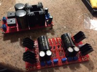
Completed BA3 board
BA3 board is assembled and ready for testing. Built a dual rail power supply using surplus Lm338 regulators and adjusted for each rail at 24 VDC. Got a variac for safe testing. Set the bias pots for zero value and P3 at midpoint.
Will fire up the board tomorrow and report. Thanks to this build guide thread and advice from the forum members and Papa for the design.
Cheers.
Attachments
BA3 board is assembled and ready for testing. Built a dual rail power supply using surplus Lm338 regulators and adjusted for each rail at 24 VDC. Got a variac for safe testing. Set the bias pots for zero value and P3 at midpoint.
Will fire up the board tomorrow and report. Thanks to this build guide thread and advice from the forum members and Papa for the design.
Cheers.
The board works flawlessly. Biases to 45mA. No problem. Did not hear yet. Will need to remove my B1 and mount this in the preamp cabinet.
Cheers.
- Home
- Amplifiers
- Pass Labs
- The BA-3 as preamp build guide