OK that was my conclusion from other readings, just wanted to my sure I did not make any mistake and get the magic smoke once moreincrease R13

should I understand I have to eliminate input buffer in the input of F4 ZM ??also ..... think about buffer on BA3 stage output
.......
should I understand I have to eliminate input buffer in the input of F4 ZM ??
no
just try same one in preamp case
Jlop,
your Tannoy hpd315 has a sensitivity around 90dB/W @ 1m
i.e. you input 2.8Vac and you will get ~90dB when measured at 1m.
input 10W and you will get ~100dB@1m
Increase your listening distance to ~8ft (2.4m) and the SPL will be around 92dB. Listen in stereo and you get an extra 3dB.
so for 95dB @ 8ft you need an input of ~3.16*2.83Vac ~ 9Vac
That's equivalent to 10W+10W
Using that 9Vac you can calculate the required input to the amplifier using the standard gain of that amp.
If you can double the output to 18Vac (without clipping either the pre/source or the amp) you can get another 6dB from 40W+40W (4times the power = double the voltage = +6dB)
Last edited:
PS-12 chassis ground question.
The attached photo is from 6l6's excellent BA-3 build guide. There is a ground wire shown in this photo that is attached between the PS-12 d.c. GND and the chassis, and has a resistor attached at the chassis end.
There is no mention of this connection in the text of the build guide, and said wire is not shown in the other photos of the power supply.
My questions: what is the purpose of this connection? Should I include it? What value resistor was /is used?
TIA,
John
Attachments
The attached photo is from 6l6's excellent BA-3 build guide. There is a ground wire shown in this photo that is attached between the PS-12 d.c. GND and the chassis, and has a resistor attached at the chassis end.
There is no mention of this connection in the text of the build guide, and said wire is not shown in the other photos of the power supply.
My questions: what is the purpose of this connection? Should I include it? What value resistor was /is used?
TIA,
John
Good question, I didn't notice that previously, will have to open up my case to check. Find it hard to believe I missed that!
Russellc
Just saw a note that says "also not shown, I took a led and resistor from v+ to ground as a power indicator" on a pic or two before that one, maybe that is it?The attached photo is from 6l6's excellent BA-3 build guide. There is a ground wire shown in this photo that is attached between the PS-12 d.c. GND and the chassis, and has a resistor attached at the chassis end.
There is no mention of this connection in the text of the build guide, and said wire is not shown in the other photos of the power supply.
My questions: what is the purpose of this connection? Should I include it? What value resistor was /is used?
TIA,
John
In my view the much more important question should be:The attached photo is from 6l6's excellent BA-3 build guide. There is a ground wire shown in this photo that is attached between the PS-12 d.c. GND and the chassis, and has a resistor attached at the chassis end.
There is no mention of this connection in the text of the build guide, and said wire is not shown in the other photos of the power supply.
My questions: what is the purpose of this connection? Should I include it? What value resistor was /is used?
TIA,
John
Is that resistor SAFE?
What does that resistor do to the ROUTE that FAULT current may have to pass.
I also note that the Floor of the box is connected to PE using a non dedicated bolted fixing.
How well is the side panel electrically connected to PE? and the front panel, and the lid?
Are the anodised panels safely interconnected?
Is that resistor SAFE?
I think so. That said, a CL-60 would be a better choice. Or a pair of 10A diodes connected in parallel but with one cathode pointing opposite of the other.
If there is no problem with ground loops or ground noise, any of those options can, of course, be omitted.
I also note that the Floor of the box is connected to PE using a non dedicated bolted fixing.
Safety earth is connected directly from the IEC to that bolt. Said bolt has a star washer digging into the chassis floor, and the other connections are the transformer shield (purple) and signal ground, by way of the 10R resistor, to lift the signal off chassis.
How well is the side panel electrically connected to PE? and the front panel, and the lid?
Are the anodized panels safely interconnected?
They are as well connected as the screws and metal holding it all together can make it.
Last edited:
I think so. That said, a CL-60 would be a better choice. Or a pair of 10A diodes connected in parallel but with one cathode pointing opposite of the other.
If there is no problem with ground loops or ground noise, any of those options can, of course, be omitted.
Safety earth is connected directly from the IEC to that bolt. Said bolt has a star washer digging into the chassis floor, and the other connections are the transformer shield (purple) and signal ground, by way of the 10R resistor, to lift the signal off chassis.
They are as well connected as the screws and metal holding it all together can make it.
6l6' what is that setup for, and if it needs a CL-60 fine, but what is answer to original question and should I add it?
Thanks,
Russellc
Don't eat the Yellow Snow !!
catch 22 is .......... audio gnd (being tied in some way to xformer secondary) must be in some proper way connected to safety gnd**
at least just because we are not usually making so called double class isolated gadgets , so there is (slightest ,indeed ) possibility of mains voltage ooking to secondary side
prior to laughing ....... just recollect memory of how many guitarists you heard being almost (or fully) electrocuted by guitar ......... due to ooked amp......
** so, said link must be more current-wise capable than mains fuse
conclusion - plain 10-15R resistor is ............ dust in the eyes solution , unless having gargantuan power , in range of 100W upwards
diodes/Graetz/cap or NTC is proper and mature solution
Last edited:
catch 22 is .......... audio gnd (being tied in some way to xformer secondary) must be in some proper way connected to safety gnd**
at least just because we are not usually making so called double class isolated gadgets , so there is (slightest ,indeed ) possibility of mains voltage ooking to secondary side
prior to laughing ....... just recollect memory of how many guitarists you heard being almost (or fully) electrocuted by guitar ......... due to ooked amp......
** so, said link must be more current-wise capable than mains fuse
conclusion - plain 10-15R resistor is ............ dust in the eyes solution , unless having gargantuan power , in range of 100W upwards
diodes/Graetz/cap or NTC is proper and mature solution
So basically a CL-60 to ground like on the BA-3 Power amp's supply...
Russellc
always simplest ........ and most effective solution
if in doubt , read Papapapers
Thanks
Russellc
I use CL60, but Rod Elliot has some interesting stuff about ground lifting:
Earthing (Grounding) Your Hi-Fi - Tricks and Techniques
Earthing (Grounding) Your Hi-Fi - Tricks and Techniques
I use CL60, but Rod Elliot has some interesting stuff about ground lifting:
Earthing (Grounding) Your Hi-Fi - Tricks and Techniques
......
diodes/Graetz/cap or NTC is proper and mature solution
Question for you guys who already have the BA-3 front end put together:
How hot are you biasing the front end? The schematic calls for 45ma (1V across 22R), but hints that you can go up to 100ma easy. Bias is free. I'd like to go higher. Any experience raising the bias here? The board is not exactly laid out well for bigger sinks but I have some aluminum bar stock I could work up into bigger sinks.
How hot are you biasing the front end? The schematic calls for 45ma (1V across 22R), but hints that you can go up to 100ma easy. Bias is free. I'd like to go higher. Any experience raising the bias here? The board is not exactly laid out well for bigger sinks but I have some aluminum bar stock I could work up into bigger sinks.
Pass DIY Addict
Joined 2000
Paid Member
With small sinks that fit the output devices, 45mA makes the sinks plenty warm. As you point out, the board is not really designed to take it much higher, but I'm sure there are clever solutions to dissipating more heat.
Pass DIY Addict
Joined 2000
Paid Member
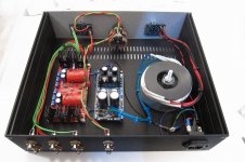
In time for Halloween here in the US, I present my Franken-BA3 preamp. It has been a long time in the works and it has changed dramatically from when I first started.
I started with a DCB1 board from Salas that later ended up being cut in half (sorry, Salas!) so all the blue board does is manage input switching and volume control. I have four inputs, switchable by remote control (green PCB with the large IC in the bottom of the image). One problem is that the DCB1 runs on 12v and the MV-04 remote unit (from ebay) runs on 5v. Because the 5v remote board won't drive the 12v relays on the DCB1, I had to string them together. I removed the RCA inputs from the MV-04 relay board and tied them to the input selector on the DCB1 with a small ribbon cable.
The three PCBs on the left of the image are the power supply for the LDRs (thanks, Uriah) that are attached to the DCB1 for volume control. Since the overall power supply provides about 36VDC, I used a series of diodes (small PCB in bottom right) to drop some voltage, then into a bank of power resistors to drop additional voltage, so the regulated power supply (green PCB, middle left, another Salas design) receives only 15v input. The green PCB provides a regulated 5v power supply that goes into the tan PCB in the top left that is the actual variable power supply to the LDRs that control the volume on the hacked DCB1 board.
The blinding set of LEDs in the middle are positive and negative Tracking Pre-Regulators (thanks for the link, Jim) that provide +/- 27VDC to the BA-3 board. Each regulator uses military-grade LT317A regulators and nine 3v LEDs as the voltage reference. The first regulator in the pre-regulator gets a bit warm, even with the sink installed. The second regulator chip stays a bit more cool. The sinks on the BA-3 also get a bit warm, but not to the point where it causes any concern. The caps in the BA-3 are Obligato 6.8uF film and foil.
A first test revealed a bit of hum in the audio chain, so I re-did the grounding scheme as a star ground which completely eliminated the hum. Overall, I have four inputs, two outputs (separated with a 68R resistor - thought I could drive a sub from this set of outputs at some point in the future), remote control input switching, and just a bit more work to do in order to enable the remote control for the volume.
On the right side of the chassis is a 200VA transformer (probably a bit of overkill) and a pair of 15,000uF caps for the primary power supply. All AC voltage is on the right side of the divider and all DC voltage is on the left side of the divider.
Once the remote volume is finished, I can close the chassis and add a nice wood panel to the front to dress it up a bit. Ultimately, the BA-3 will be a dedicated pre to my turn table and Pearl II build.
I suppose the last trick is to figure out how to properly set P3 with my meager set of measurement equipment.
Attachments

Last edited:
- Home
- Amplifiers
- Pass Labs
- The BA-3 as preamp build guide